You are using an out of date browser. It may not display this or other websites correctly.
You should upgrade or use an alternative browser.
You should upgrade or use an alternative browser.
sveinutne
Member III
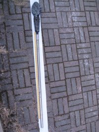
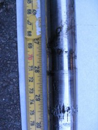
Had a look at the propeller shaft, and could see a lot of wear where the packing box had clamped around the shaft. It was about 70 cm from the propeller. I see several options.
- Move the propeller shaft in one or two cm. It can be done by using a smaller offer anode around the shaft.
- Move the propeller shaft further out, but this could lead to too much play and vibration on the propeller.
- Turn the shaft around, if I can get it loose from the propeller.
Attachments
-
 Propeller shaft-s.jpg80 KB · Views: 48
 -
 shaft-70cm-s.jpg58.4 KB · Views: 47
Placement of the propeller is very important and there is often very little movement fore and aft available for the best fit. On a sailboat, the minimum clearance from the propeller tip to the hull should be no less than 10-12% of the diameter of the propeller with something more like 15% being better yet. At the same time, you don't want the propeller shaft to be extending much more than about 3 inches from the aft edge of the strut or whipping in the shaft can occur. So, as you look at moving your shaft in or out/changing it's length, you need to be sure you maintain some of these basic clearances.
A final thought, looking at the pictures of your prop. shaft and the scoring and possible crevice corrosion that could be going on, I'd just get a new one of the proper length for your installation after you have finalized your engine position and had all the other mounting issues resolved. Probably would run about $150 here - not sure what it would cost in your part of the world.
A final thought, looking at the pictures of your prop. shaft and the scoring and possible crevice corrosion that could be going on, I'd just get a new one of the proper length for your installation after you have finalized your engine position and had all the other mounting issues resolved. Probably would run about $150 here - not sure what it would cost in your part of the world.
Last edited:
Sven
Seglare
At the same time, you don't want the propeller shaft to be extending much more than about 3 inches from the aft edge of the strut or whipping in the shaft can occur.
Which is something that Lew worried about and we do too. I would guess that on the E39B the distance is more like 8".
I have no idea how that came to be, "but there you have it, there it is."
-Sven
sveinutne
Member III
The former owner Ed Collins has been very helpful and given me a lot of new information about the boat. From one of his e-mails:
The V drive acts as one bearing while the one in the hull acts as the other. The one in the hull is called a "cutlass bearing". That one has ALWAYS been hard to remove. I let the guys at the boat yard do it, and they always cursed at me for it.
I just remembered that the "packing gland" had some sort of rubber hose that connected it to the hull. I would replace the rubber AND the clamps as I never did in the 11 years that I owned the boat.
Good luck
Ed
-
He also told me the hull number was 26, and a lot of other details and history of the boat. I will inspect the cutlass bearing with an endoscopy instrument, and see what it looks like. I am not so keen on replacing it yet. With the new hydraulic drive the speed on the propeller shaft might be different. If the condition on the bearing is not too bad, I will try to use it this summer. It will only be a short season with not too much use. No long trips. It will be more like small test runs, so when I know the rpm on the engine and propeller shaft and got some feeling for what is best rpm, it might be time to replace the propeller, propeller shaft, cutlass bearing and packing gland. If I need to get down the rpm on the propeller, I might go for a three blade propeller. But this will be next winter. Now I need to decide what to replace for only 4 months use. I think I will find a slimmer offer anode so the shaft will be 2 cm closer to the hull. There should be room around the propeller for this, but I will check it. Also the rubber and the clamps will be replaced with new. The stuffing box will be inspected.
But if the old propeller is working fine, I think I will keep it. When it is closed it looks like it will give very little drag. I think a new three blade will give more resistance when sailing.
Last edited:
Which is something that Lew worried about and we do too. I would guess that on the E39B the distance is more like 8".
I have no idea how that came to be, "but there you have it, there it is."
-Sven
Just doing some double checking and distance from the aft edge of the strut to the front edge of the propeller is often targeted for about 20% of propeller diameter. So this would mesh with what I had remembered of shooting for about 2-2.5" with a prop. in the 12-13" diameter range and not exceeding 3".
sveinutne
Member III
I like the look of new teak, but that might be because I have never been the owner of a sailboat with teak deck before. Yesterday was worm by our standards, and we got some sun, so a lot of boat owners were in the marina working on their boats making them ready for the new season. After talking to several with a lot of teak on their boats, I started to rethink my plans about using a lot of teak. The teak looks nice when it is new, but after some exposure to sunlight it will look gray and dirty.
To prevent that from happening one can sand it down before every season, or put on 5-10 layers of UV protective varnish. What ever you choose, teak is a lot of work if you want it to stay looking good. Also teak with varnish on is very slippery.
The friction padding that I got on the deck was getting good comments from a lot of boat owners. For safety on deck it might be the best.
So now I will adjust my teak planes a little bit. I still want teak in the cockpit, but only on the seats. The cockpit floor will get new friction padding instead of teak.
Now the problem is to find a supplier that will deliver friction padding as big as I need them. I can order it from <?xml:namespace prefix = st1 ns = "urn:schemas-microsoft-com ffice:smarttags" /><st1:country-region w:st="on"><st1
 lace w:st="on">Germany</st1lace></st1:country-region>, but it is only 1200 x 900 mm. and I will need 1450 mm in length. I guess this has to do with transport. Boxes less then 1200 mm in length cost very little to transport. So then I will have to glue two pieces together. Not my dream start for a rebuild, but we will see how good the joints can be.
<?xml:namespace prefix = o ns = "urn:schemas-microsoft-comfficeffice" /><o> </o>
TREADMASTER - Anti-Slip Deck Covering - Diamond Pattern
<o> </o>
http://www.svb.de/index.php?sid=e891e0fbbc5b8c8a86d9ebcdef2eb5fd&cl=details&cnid=11909&anid=731
<o> </o>
This diamond Pattern is close to what I got, and it is 3 mm thick.
As an alternative I can use this:
<o> </o>
http://www.svb.de/index.php?sid=e891e0fbbc5b8c8a86d9ebcdef2eb5fd&cl=details&cnid=11909&anid=733
<o> </o>
It is only 2 mm in thickness, and is sold in length up to 10 meters, but might be almost as good.
<o> </o>
Maybe I order a test piece of the last one and try it in the cockpit floor. If it looks ok, I might use it also on deck.
Regards
Svein
<o> </o>
To prevent that from happening one can sand it down before every season, or put on 5-10 layers of UV protective varnish. What ever you choose, teak is a lot of work if you want it to stay looking good. Also teak with varnish on is very slippery.
The friction padding that I got on the deck was getting good comments from a lot of boat owners. For safety on deck it might be the best.
So now I will adjust my teak planes a little bit. I still want teak in the cockpit, but only on the seats. The cockpit floor will get new friction padding instead of teak.
Now the problem is to find a supplier that will deliver friction padding as big as I need them. I can order it from <?xml:namespace prefix = st1 ns = "urn:schemas-microsoft-com
ffice:smarttags" /><st1:country-region w:st="on"><st1lace w:st="on">Germany</st1lace></st1:country-region>, but it is only 1200 x 900 mm. and I will need 1450 mm in length. I guess this has to do with transport. Boxes less then 1200 mm in length cost very little to transport. So then I will have to glue two pieces together. Not my dream start for a rebuild, but we will see how good the joints can be.<?xml:namespace prefix = o ns = "urn:schemas-microsoft-com
fficeffice" /><o> </o>TREADMASTER - Anti-Slip Deck Covering - Diamond Pattern
<o
> </o>http://www.svb.de/index.php?sid=e891e0fbbc5b8c8a86d9ebcdef2eb5fd&cl=details&cnid=11909&anid=731
<o
> </o>This diamond Pattern is close to what I got, and it is 3 mm thick.
As an alternative I can use this:
<o
> </o>http://www.svb.de/index.php?sid=e891e0fbbc5b8c8a86d9ebcdef2eb5fd&cl=details&cnid=11909&anid=733
<o
> </o>It is only 2 mm in thickness, and is sold in length up to 10 meters, but might be almost as good.
<o
> </o>Maybe I order a test piece of the last one and try it in the cockpit floor. If it looks ok, I might use it also on deck.
Regards
Svein
<o
> </o>sveinutne
Member III
The restoration of Ericson 41 is a flexible project with a lot of changes in plans as the project evolves. I wanted to use more teak, but after some more information, I see teak got a lot of negative sides. Also some of my friends mention the preservation of rainforest. I have to admit, that it was not on the top of my list of concerns. But how difficult it is to keep the teak looking good is more important. Also that it will be more slippery if I choose to vanish it to keep the color. So now it might only be the last part of the side board that will get some new teak. I will take a picture of it later, so you can see what I am talking about. I think what is used today is one large piece of teak. It must be 3.2 meter long and 30 cm wide and about 2 cm thick. It is what you lean your back against when sitting on the sides in the cockpit. The last 1.5 meter is very fragile because it is sticking up like a feather with no support. If someone steps on it, I am afraid it will break. I will reinforce that last part with 12 mm thick teak glued on the old teak, so it will be stronger.
The rest of the cockpit will get first some new layers of fiberglass, and then new friction padding. If this is a success, I plan on doing the same with the rest of the boat. Then it is important to get larger pieces so I can use the original sizes Ericson used. http://www.svb.de/index.php?sid=7e08e13ad3a427af7a06125c4a7b1e1d&cl=details&cnid=11909&anid=733
TBS - Non-Slip Deck Covering
This Non-Slip Deck Covering is made of polyurethane and polyurethane pellets. Offers incredibly high non-slip properties under all circumstances. It's highly resistant against sunlight, seawater and oil. Suitable for all types of decks (steel, glassfibre, wood and aluminium). The soft surface of this covering offers a maximum of comfort and safety. UV-resistant in all four colors. Roll with: 128 cm. Thickness: 2 mm. Weight: 2,5 kg / sq.m. Sold per meter and as 5 m or 10 m roll. I wanted the light blue color, but it might be the one marked as Light Grey (Hell grau) that is closest to it. I think I will order 5 meters of it and try it in the cockpit, and if I like it, it will be the same on all the parts that got friction padding today
Last edited:
sveinutne
Member III
Hopefully the new engine will arrive tomorrow. Have called SVB in Germany and asked for samples for nonskid covering. I think it will be TBS or this new Antislide. Teak is still a question. On most boat I see they have teak on the seats in the cockpit, and it must be a reason for this. Teak with vanish will be very slippery and might crack in the vanish. Teak with oil will be very gray and will look dirty. Personally I like new teak very much and it feels warm to sit on, but how to keep it look good might be the problem. Also it will take more time to make all the pieces of teak and get it right.
Maybe I will wait with more teak and use Antislide on deck and also in the cockpit this first year, and later when I have decided, I might put in teak on the seats in the cockpit if I feel that to be the best. I am also planning to adjust the boat so I can sail it single handed. If I will sail it with my wife, it would be nice if she could go downstairs and make some food or do other things while I take care of the sailing, so I plan to have electric winch for the Genoa and the main sail that can be controlled from the seat behind the steering wheel.
Maybe I will wait with more teak and use Antislide on deck and also in the cockpit this first year, and later when I have decided, I might put in teak on the seats in the cockpit if I feel that to be the best. I am also planning to adjust the boat so I can sail it single handed. If I will sail it with my wife, it would be nice if she could go downstairs and make some food or do other things while I take care of the sailing, so I plan to have electric winch for the Genoa and the main sail that can be controlled from the seat behind the steering wheel.
Last edited:
sveinutne
Member III
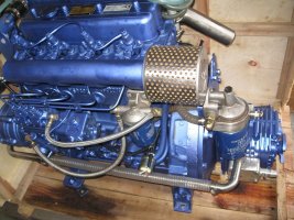
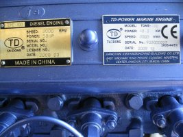
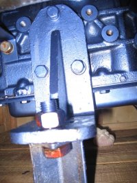
Got the new 58 hp engine today, but I might have to move the true hull pipes from the cockpit drain. I might keep it as it is, but then the engine is getting very close to the cabin wall. By moving it back 10 or 20 cm, I get plenty of space and then have room for good sound isolate of the engine. Will consult a boat designer just to be sure it is OK to do this.
Attachments
-
 IMG_5914-s.jpg119.6 KB · Views: 46
 -
 IMG_5909-s.jpg115.2 KB · Views: 47
 -
 IMG_5910-s.jpg71.2 KB · Views: 47
sveinutne
Member III
Need to do some more measuring and hard thinking. I will save some work, if I can install the engine without making new hole through the hull, but if I later get problems because of lack of space, it might be better to take the extra work now. The good thing about the hydraulic drive is that it is giving me more flexibility. If I move the engine back 20 cm, I will get space for extra sound isolation and other things. If I later decide to put in a new galley, I will have more room and freedom to do that. So at the moment I am leaning toward moving the engine back 20 cm.
sveinutne
Member III
I have been swatting this last two days because the engine I have bought is too large for the space, or almost too big. When I look at the pluming going trough the hull, I do not want to make new holes in the hull. But today I think I have found the solution. I only need some cm for the engine to get clear of the 2” tubing. My solution to the problem might be to put in a 45 degree bras tubing at the first joint closest to the hull. In stead of the tubing leaning 20 degrees towards the engine, it will be leaning 25 degrees away from the engine. Then I will get plenty of room higher up. I only need to move the fan belt for the generator and it will all be OK with the engine. I might have to replace the fan belt with one that is slightly longer. So now I am smiling again.
sveinutne
Member III
The next will be to make better foundation for the engine. I professional bout builder recommended that I molded in a 5 till 10 mm thick soft iron plate with 5 layers of fiberglass over, and then made treads for the bolts holding the shoes for the engine.
After that I will have to take of the transmission and put in the hydraulic pump where the transmission was. Then mount the transmission directly to the propeller shaft down in the bilge.
After that I will have to take of the transmission and put in the hydraulic pump where the transmission was. Then mount the transmission directly to the propeller shaft down in the bilge.
sveinutne
Member III
The size of the new engine has given me several days of speculation. The pipes going true the hull, is so close to where the belt for the generator is going, so even if I might be able to squeeze the engine in, I would feel much better with the engine 10 cm further back, and 10 extra clearance for the belt. So the pipes should be moved back 20 cm.
I have never removed or installed such through hull tubing’s, so before I start to do anything stupid, it would be nice to hear what others have done or experienced when trying to remove this 2” tubing. If it is possible to reuse the tubing, it would be nice, but maybe this is a good opportunity to put in new tubing with stop valves at the same time.
I have never removed or installed such through hull tubing’s, so before I start to do anything stupid, it would be nice to hear what others have done or experienced when trying to remove this 2” tubing. If it is possible to reuse the tubing, it would be nice, but maybe this is a good opportunity to put in new tubing with stop valves at the same time.
Moving a hole in your hull
To me, you are describing the changing of a location of a thru hull fitting by about 8".
If so, you need to glass in the old hole in the hull by tapering the edges and laying in circles of roving until you match or exceed the original hull thickness. Personally, I would use epoxy for this for maximum strength and adhesion. There are some great threads on this site regarding installing a new thru hull "sea cock" with backing plate.
Here is a good thread, containing a link to another good thread, on this.
http://www.ericsonyachts.org/infoexchange/showthread.php?t=6244&referrerid=28
Regards,
Loren
The size of the new engine has given me several days of speculation. The pipes going true the hull, is so close to where the belt for the generator is going, so even if I might be able to squeeze the engine in, I would feel much better with the engine 10 cm further back, and 10 extra clearance for the belt. So the pipes should be moved back 20 cm.
I have never removed or installed such through hull tubing’s, so before I start to do anything stupid, it would be nice to hear what others have done or experienced when trying to remove this 2” tubing. If it is possible to reuse the tubing, it would be nice, but maybe this is a good opportunity to put in new tubing with stop valves at the same time.
To me, you are describing the changing of a location of a thru hull fitting by about 8".
If so, you need to glass in the old hole in the hull by tapering the edges and laying in circles of roving until you match or exceed the original hull thickness. Personally, I would use epoxy for this for maximum strength and adhesion. There are some great threads on this site regarding installing a new thru hull "sea cock" with backing plate.
Here is a good thread, containing a link to another good thread, on this.
http://www.ericsonyachts.org/infoexchange/showthread.php?t=6244&referrerid=28
Regards,
Loren
sveinutne
Member III
This site is very good. I get so much useful information from this place. With all this information laying around in the different treads, and with so helpful people, it is a joy to be here. To patch a hole with epoxy and multiple layers of fiberglass should be OK for me to do. What I wonder about is how I should start removing the old pipe. If the ball valve is in good condition I might be able to reuse it, but I will check it first.
sveinutne
Member III
Svein,
I think I remember someone that looked at your boat before you bought it mentioning that there was a non skid membrane glued down. The raised area that is left might be the factory molded in non skid.
Can you clean that area up and paint with some non skid paint?
I am looking at this non skid paint now, and will try it on some parts.
sveinutne
Member III
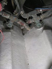
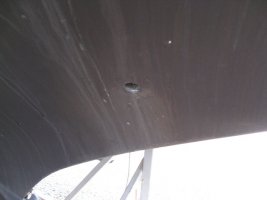
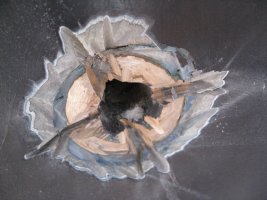
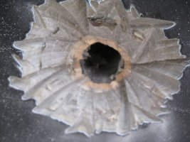
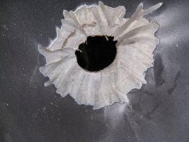
I have spent two weeks thinking about what to do with the position of the engine and what to do with the pipes going through the hull. When I finely decided to move the engine back and then also move the pipes back 20 cm, the job to remove it was quicker and easier then I first had thought. This is not the recommended way to do it if you want to use the same holes or pipes over again. Also I wish I had not grinded the hull and pipes as much as I did. I think I could have stopped after half the grinding and used more force on breaking the pipes loose instead. Then I could have grinded the second half from the inside. Now I still need to grind from the inside to get good starting position for the fiberglass and epoxy, but the hole will be larger then needed.
I looked at my watch and noticed it took me less then 10 min from I started on the second pipe, till it was out of the boat. So knowing what to do and how to do it takes more time then doing it sometimes.
Also after inspecting the pipes, I see it is not a great loss. It was time for replacement in any case.
PS. I think the size of the pipes are 1 1/2 inch
Attachments
-
 pipe-1-s.jpg63.7 KB · Views: 42
 -
 pipe-2-s.jpg107.5 KB · Views: 50
 -
 pipe-3-s.jpg94.9 KB · Views: 42
 -
 pipe-4-s.jpg109.3 KB · Views: 46
 -
 pipe-5-s.jpg155 KB · Views: 47
Last edited: