E35-II AC/DC Panel-Wiring Upgrade

chaco

Member III
Well....it's that time again ! Gotta rewire and install new AC/DC panels for
the ole 74' E35-II. I have seen various panel arrangements and I am looking
at moving the whole gang to the NAV Station locker area :confused:
My connected load requires (4) AC Breakers + 30A Main and 20 +/- DC
Breakers + 100A Main. Have the AC Panel (thank you Minneys !) and
am looking at a BlueSea DC Panel with Digital Multimeter.
Am outfiitting for extended Cruising (Baja....Costa Rica....)
Will have the (1)12V Start Battery / (4)6V House Battery - Interconnect
wiring and switch system.
As anyone has rewired one of these beasts....sure would like some advise.
Love that Home Depot AC Panel under the sink :D

Thanks to you all for the great help in outfitting these beautiful creatures.
:egrin: :egrin: /) /)
 

Ray Rhode

Member III
Don't have a specific suggestion for your 35-II, but when I rewired my 35-III I took a look at the DC panel and realized that there were a number of things that did not need circuit breaker/switches. I installed a fuse block and replaced the CBs for things like the GPS, VHF, AM/FM, etc. These things have their own ON/OFF switch and only need fuses for protection. I was able to save on the cost of the DC panel and fit it into a smaller space.

Food for thought.

Ray Rhode
S/Y Journey
E35-III, #189
 

Mike.Gritten

Member III
Ray,

I am in the middle of the same project. We have chosen to put the AC/DC panels over by the nav table, but, not in the factory locker/shelf area - we are taking the forward part of the storage area above the quarter-berth. I have the AC panel in and running great. You're right about the original panels. I am sure they are dealer installed not factory, but mine, like yours looked like stock metal cased home units. In fact, the reason we did the AC first, was that two of the breakers in the original box had failed (some bizarre brand/style that is not available any longer) and we needed the circuits for heating in the winter. It was a relatively easy job with good advice from Nigel Calder's Electrical and Mechanical book (highly recommended!). I epoxied a piece of mahogony ply and installed it in back of the rail on the shelf. It can be easily removed by taking out two 1/4" nuts and bolts. I chose the Blue Seas AC main panel with 30A main breaker and 3 15A breakers installed. I installed 1 additional 15A breaker leaving me with 2 spare for later additions. I wired my water heater and Statpower battery charger to their own 15A breakers and installed several new ground fault protected outlets down each side of the boat, wiring port-side plugs to one breaker and starboard-side plugs to another. I replaced all the old AC wiring in the boat and installed a galvanic isolator at the shore power connector for safety. The system has worked perfectly! I have purchased an additional 30A main breaker to install next to the shore power connection as Mr. Calder says that it should be within 10 feet of entering the boat and my current design has about 18 feet of 10 gauge before the panel. In hindsight, I would probably opt for the dual source main breaker panel from Blue Seas, installed by the shore power connector, to allow an easy switch to a larger inverter to power the existing boat systems when not attached to shore power. I could have then put in a simpler panel with no main breaker at the nav station.
As far as the DC panel goes, I will require either 17 circuits plus some spares, or 13 (plus spares) if we opt to get a cool nav light panel which graphically displays what lights you're showing.
I couldn't use the existing locker/shelf as I have already taken that area for other things i.e. Navman repeater, VHF radio, SSB radio, stereo and CD changer, remote charger control panel, handheld VHF charger station. I will try and take some pics of the work so far. The intention is finish the panel work and then stain/varnish all the ply to match as closely as possible to the existing finish. Overall I am very pleased with my redesign.
 

Glyn Judson

Moderator
Moderator
AC/DC Blue Sea Panel insallations

Mike and all, I too have upgraded my original Ericson AC/DC panels to Blue Sea that are now located at the nav station in our E31. Here are a couple of things I did to mine that you might want to consider, if applicable. My guages are analog dials and I back lit them using the extra snap-off, green LED's from the switch ID's. I scraped the circuit trace down to the copper foil and soldered wires to them. It was then a simple matter of mounting the strip above the back side of the dials so that when I flip the panel lights on, they light up too. I avoided using a separate circuit breaker switch for them by combining the LED's to my running lights, the thought being that if it were dark enough to require the running lights, it would certainly be too dark below to see the panel switches and dials. I made the upper right switch on my 13-switch DC panel the one for the running and panel lights so I could easily feel for it in the dark. And that's about it. Happy New Year to all, Glyn
 

Tom Metzger

Sustaining Partner
Ground fault protected outlets

Mike.Gritten said:
...and installed several new ground fault protected outlets down each side of the boat, wiring port-side plugs to one breaker and starboard-side plugs to another.

The ground fault interrupters will protect all outlets in series downstream, so you could have just used two GFIs, one port and one starboard.
 

jmoses

Member III
E-35 II DC Panel

Glynn,

After ripping almost all the wire (AC and DC) out of my '72 E-35 MKII, I'm planning on a new DC panel installation that will bring the boat up to the 21st century. The AC system is complete with all new tinned wire combined with Blue Sea Systems #8029 (Mains with polarity) and an 8 position AC sub-panel with volt and amperage gauges. Now there are GFCI outlets in convenient locations, the battery charger meets code and the old AC fire hazard wiring is gone!

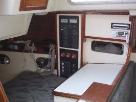
The new AC panels are all mounted near the original DC panel over the ice box area. Since my shore cord connection is in the stbd rear cockpit area, this made sense for the AC panels, notably the AC mains interupt. As an aside, the AC mains breaker is required to be within 3 meters of the shore cord connection (measured along the conducter), so this area made sense for the AC install (see ABYC E11.12.2.9.3). In addition, it is not recommended to co-mingle AC and DC circuits and panels as it is possible to have an arc or short circuit from AC to DC and cause a hazardous situation (more ABYC stuff).

As you are probably more than aware, the old Ericson DC panel is woefully outdated with the toggle switches and fuses, not to mention the 35 years of 'elctricians' who worked on it with a hatchet and electrical tape. So, I have speced out a new install that will mount in front of the nav station bulkhead in the area of the port aft storage shelf.

What I could never figure out is why Ericson put the batteries on the port mid-ship area and the DC panel located about 20 feet (wire run wise) away on the stbd aft mid-ships. To top it off, someone ran all the heavy battery cables to a Perko "OFF/Bat 1/Both/Bat 2" switch mounted next to the DC panel and back. I pulled out about 50 feet of red and black battery cable (untinned) from that mess. The Perko switch is now temporarily located on the Nav panel bulkhead tucked up in the outboard coner until the proposed DC panel is nearing completion.

Prior to instigating the new DC wiring, I removed the small Ericson battery box and fabricated a much larger box that now holds two GRP 31's (or two 6 V batteries if desired) instead of the designed GRP 24's. This appraoch has increased bat. capacity tremendously with little weight penalty (!) and offered the option of 6V batteries later is desired.

The area for the new DC panel is close to the current battery installation, close to the engine (and alternator), readily visible, away from water spray, not too out of the way for operation yet not in a location where someone could mistakenly fall/lean against it shutting off circuits in rough seas/bad WX.

It has been a real job stripping out all the Ericson (and added) wires to be replaced with tinned cables. I have installed temporary fuses in the DC circuits that are freshly re-wired until the main DC panel is finished. It's kinda like widening a road and keeping the traffic flowing until it's done.

Now I'm in the planning stages of making an enclosure that will be built into the last 18" of the shelf area behind the port settee and use the nav station bulkhead as the aft side of the panel's box. This way, I have plenty of room to run wires by feeding them from underneath and not crowd them or make a rat's nest. Also, the front the panel can be mounted on a hinge so it may drop down for new wiring, new breakers, maintanance or what ever. It will be totally enclosed except for the hinged front panel.

ANyway, I have decided on the Blue Sea Systems panels, the location and basic design. I just need to come up with close to $1,000 to finish off the last stage - building and wiring the panel!

I keep an eye on ebay as there are occasionally good deals on Blue Sea Systems panlels on there.

John M.
 

Mike.Gritten

Member III
Tom,

Yes, I understand the GFCI thing where all outlets downstream have the same protection, but, all the outlets needed updating and replacing anyway so I figured I would just standardize and install them all as GFCI outlets. It gives me lots of spares since they are all the same.
 

chaco

Member III
AC/DC Rewire Bliss

Thanks all, we are having FUN now ! :D
I got some great panel location ideas from looking at ALL the interior
pics of E35-II for sale in our "For Sale & Wanted" site (maybe (20).
Found one in Venezuala with the panels in the Nav Station locker as
we have discussed. I like the AC/DC Panel seperation idea and this will
work well with my arrangement. Now for a few details :devil:
1. How are you wiring your batteries? 4-way switch or Parallel House/Start
with (3) on/off switch?
2. What are your battery bank specs?
3. What are you using for AC stray current protection? Galvanic isolator?
4. What loads are directly connected to the battery positive bus with
remote breakers for constant power(cd player brain) and which loads go
to the new spiffy panel with central breakers and interuptable power?

Thats ENOUGH for now :p
 

jmoses

Member III
Details

1. How are you wiring your batteries? 4-way switch or Parallel House/Start
with (3) on/off switch?

- I re-wired in the 4 way Perko switch (OFF/Bat 1/Bat 2/Both)

2. What are your battery bank specs?

- I ripped out the old cheezy fiberglass battery pan (E-35 MKII) and built a large epoxied plywood box to replace it. I now have two group 31 batteries installed with the potential for two 6 V batteries to replace them. The amp hours have increased 60% from the small two group 24's 150 Ah to the new two group 31's 220 Ah. The weight penalty was minimal @ 30 more pounds.

3. What are you using for AC stray current protection? Galvanic isolator?

- No galvonic isolator as I have not had a problem on my boat with stray currents. I have ripped out all the old wiring and have cleaned up the boat's electrical situation. Also, my marina doesn't have a problem with stray currents as my zincs last almost two years.

4. What loads are directly connected to the battery positive bus with
remote breakers for constant power(cd player brain) and which loads go
to the new spiffy panel with central breakers and interuptable power?

- By using proper wiring practices, there should be very little connected directly to the batteries. Only the engine and a bilge pump (fused of course) should be directly connected. Everything else should flow through a battery switch and a breaker (or at least a fuse). The previous owner had a penchant for wiring directly to the batteries which defeats the battery selector switch! Not to mentin the nightmare of a dozen little in-line fuses mounted all over the place.


Hope that helps,

John M.
 

Ray Rhode

Member III
These specifics may not help because of our different models, but FWIW here is my set up.

I used three separate ON-OFF switches. One for the engine battery located next to the engine thru hull (in deference to my advancing Age Activated Attention Deficit Disorder). The house switch is located next to the house battery box to keep the wire runs short. A third switch is located under the nav seat, out of the way. It will connect all four batteries.

I have three Group 31 gel cells in parrallel for the house load and one Group 24 for starting. Will probably upgrade the start battery next swap.

I did install a GI even though my marina is clean. Never are sure about the ones you visit.

All DC loads pass through the house battery switch except the bilge pump float switch and the AM/FM memory. I used a fuse block for the stereo, VHF, GPS and utility outlets. I generally fused anything that had its own dedicated ON-OFF switch. The fuse block ties everything together in one place instead of a bunch of in-line fuse holders.

Ray Rhode
S/Y Journey
E35-III, #189
 

msc1212

Member II
I'm rewiring my 1970 35 this winter also. I've purchased a 13 switch Blue Sea DC panel: a Xantrex Control Panel with three phase voltage regulator for a high output alternator: a paneltronic AC panel with 3 15 amp circuit breakers. I've taken out the nav table and the small cupboard. I'm building a new cabinet that will house all of these components. I'm building a battery box which will be seated on the floor directly beneath the cabin hatch. I'm not sure what configuration of batteries I will install: atleast an 8d or possibly two for the house and a start battery. Instead of a battery switch I'm installing a BEP voltage sensitive relay with a house and start switch.

One question I have was raised in a previous reply. Why should the ac and dc be separated. There are dozens of panels for sale including Blue Sea that combine these sources. Are they unsafe? I want all of my power supplies to be in one location with breakers that can be shut down quickly. What do you think.
 

jmoses

Member III
AC/DC panel combination

Ac and DC panels are not recommended to be installed directly next to each other without some type of insulation or protection.

The reason being is that an AC wire can easly arc or short over to a DC wire and cause a massive fire, injury or death. Also, it's very easy to cross wire an AC circuit to a DC circuit when working from the rear. Think about 110 V AC running through the small wires to the radio or navigation lights. Yes, a fuse/breaker is supposed to stop this type of situation but a slow blow or incorrect fuse will not help much here.

The only recommended solution to a combined AC/DC panel is to have the entire AC portion of the panel's backside covered with a plastic or some other non-conductive cover.

Blue Sea Systems does indeed make combined AC/DC panels and they sell covers for the rear of their panels as well (part numbers # 4026 through 40310). See their catalogue or web site for more information.

With a combined AC/DC panel the rear portion of the AC panel MUST be completley covered to ensure no possibility of arcing, short circuits, or cross wiring to meet ABYC standards.

For all practical purposes, completely covering the rear of an AC panel is usually not feasible so it's best to seperate the two.

See ABYC E11.11.1.1 for more details on this issue or the Blue Sea Systems web site.

John M.
 

Glyn Judson

Moderator
Moderator
Combined or olocated AC/DC panels

John and all, I have seperate Blue Sea AC & DC panels mounted smack-dab next to each other at the nav station of our E31. I added the plastic cover you reference to the AC panel for the very reasons you mentioned. The cover encloses the entire back of the AC panel nicely with a small hole I cut providing wire access to the terminal screws. Anyone interested can email me back channel at glynjudson@adelphia.net for three photos of the installation. Glyn
 

chaco

Member III
6V or 12V House Bank

I will be installing a Balmar 712-80A alternator and external regulator in the
new wiring design. Balmar recommends a battery bank of 4X the alternator
output (4 X 80=320A +/-) for a design referance :cool:
Looking at (2) 6V Trojan T-145/260AH House Bank and (1)12V 600CCA
Start Battery. What is the advantage of the 6V House System :confused:
My only large constant load is a Norcold Ice Box Conversion 3A@12VDC.
(3A X .5 use factor X 24HR = 36AH). 260AH X .40 discharge = 104AH
storage capacity. My load will be 50AH/Day +/- . Do I need more storage
for extended cruising ?
 

rssailor

Moderator
Battery setup

Dan,
Two T-145's are a very good start to a house bank. Always figure your amp-hour capicity at 50% discharge. Balmar does recomend that you have 25% or more of your battery bank in alternator capacity. Always error on the larger size when selecting an alternator. The alternator will last longer and you will also be able to charge your battery bank quicker. This said, however flooded lead acid batteries are kind of slow when it comes to taking a charge as far as batteries are concerned.
You say that you will be using approx. 50 Ah per day. Well with your house bank, in 48 Hrs then you will need to charge. This should be ok as you will have good charging from the alternator with the MC-612 driving it. Don't forget to use a Duo charge hooked up between the house and engine bank to keep the engine battery charged up and happy. Also use a circuit breaker of 125% of the alternator's max output and locate this breaker within seventy two inches of wire length of the alternator. Good luck Ryan
 

chaco

Member III
Nice Panel !

Here is a GREAT electrical panel setup for the E35-II.
Meets all the requirements of my new wiring project.

Hey... thank you all for sharing your rewire experiences !
:egrin: :egrin:
 

Attachments

  • E35-II Panel1.jpg
    E35-II Panel1.jpg
    60 KB · Views: 162

msc1212

Member II
What about the batteries?

In my E35 1970 #110 the batteries were adjacent to the engine on the port side of the boat. I'm not sure this is where they originally were. Where should they be? Where are they on your E35? Is there a picture of your configuration? Please and thank you.

michael
 

chaco

Member III
E35-2 Battery Bank

Michael
The original battery bank is located in the port settee locker, next to the
engine. The original battery bank is (2) 12V #24 Deep Cycle (160Ah)
run back to a 4-way battery switch next to the galley sink.
I will need to build a new battery compartment in the same area for the
(2) 6V-Trojan T-145 (Marine/Golf Cart Style) house bank (260 Ah)
Will locate the (1) 12V #24 start battery in the port quarter berth locker.
 

msc1212

Member II
battery location in rewiring.

Does having the batteries in the port locker contribute to a port list in the boat? Is there someway to efficiently correct for this? Have you heard or seen the batteries built directly beneath the companionway?
 
Top