Cockpit floor - I'm assuming this ISN'T factory...

Jaybee

Cocoa, FL 1984 30+
Like the title says, I'm waist deep into rewiring and a small amount of reconfiguring on my 30+

Next project is to remove this horribly bad job of what I'm assuming ISN'T factory plywood and fiberglass mess underneath the cockpit floor.
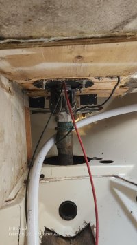
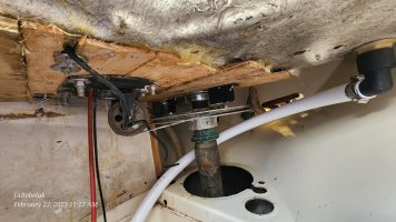
20230222_110748.jpg

20230222_111312.jpg

You can even see where it's making the rudder cables at an angle to the quadrant.

So, what's the question here you may be wondering - just making sure that this wasn't standard procedure from the factory to stiffen the floor?

In either, case I planned to put a new plywood ceiling back with thickened epoxy simply for having a surface to mount wiring, cables and hose runs to.
 

Loren Beach

O34 - Portland, OR
Senior Moderator
Blogs Author
That must have been an "interesting" part of your purchase survey!
:(
And no, it would have not left the factory that way. The EY coring in our cockpit sole was plywood, at least at the rear portion where the wheel and guard hardware was bolted down.
My SWAG (a common form of guessing) is that the sole around the wheel got spongy due to water penetrating down around the big bolts. Instead of re-coring it properly and epoxy-sealing all the holes....... someone patched it, sort of, with plywood from underneath. This lets the water continue to spread slowly throughout the remaining coring and lets the deterioration continue. (sigh)

I would remove the scabbed on ply, and then dig out the rot. All this after the steering parts are removed. (Bit of a project...)
Hard to do underneath, and easier from the top, leaving only the bottom skin of glass in place, IMO.
 

Pete the Cat

Member III
Seems obvious it is an "aftermarket" effort. I have seen some production boat floors that were shimmed with junk from the factory floor, but never anything like this. There are a lot of bad boatyards thses days, but this looks like an amateur fix. Looks like the pedestal base rotted out (not uncommon as many were mild steel) and the floor rotted as well. Looks like they used the old turning block sheaves. You have a very unpleasant project ahead and have my sympathy. I hate fixing other peoples' poor quality work. It is going to be nasty work to get that plastered plywood ground out to see what the original floor looks like underneath. Sometimes the floor core beneath the pedestal rots along with the metal base and. maybe that happened here. It is a bit difficult to get a weakened cockpit floor strong enough and maintain alignment of everything with the quadrant. I fixed one situation by burying a piece of 1/4" aluminum in place of the rotted floor and glassed with biaxial cloth. The base of many pedestals is a weak point in lots of production boats. Ericson was not the worst production yard in this.
 

Jaybee

Cocoa, FL 1984 30+
Seems obvious it is an "aftermarket" effort.

I would say that too but I must also say after digging around the boat a bit I'm not too impressed with the factory's work either. Maybe my standards are too high but I think of seaworthiness like I do airworthiness. I reckon I've flown a few shoddy planes and helicopters and am still here to talk about it. I don't think this boat will necessarily fall apart but yeah, even the non-rotted factory stuff wasn't that well put together in my two cents worth...
 

Christian Williams

E381 - Los Angeles
Senior Moderator
Blogs Author
Bob Skalkowski (Bolo) fixed a soggy cockpit issue (which sounds like the origin). Maybe he'll comment.


Pete the Cat

Member III
Bob Skalkowski (Bolo) fixed a soggy cockpit issue (which sounds like the origin). Maybe he'll comment.

Would be interesting to see what he found to be the problem. The underside looked first class in every respect.
 

u079721

Contributing Partner
This should get sorted out when you rip all that out....but right now the lead from the pulleys to the quadrant is terrible! I can't believe someone didn't look at that and realize that lowering the pulley's mounting plate would put them out of line with the quadrant. Give the cables a good going over to see if they are beginning to chafe too.
 

Bolo

Contributing Partner
Someone mention my name(s)? Yes….the soggy cockpit floor. This was noticed when it became apparent that the binnacle guard was “moving” a bit too much at its base. After further examination, below deck and under the binnacle, it was obvious that the bottom of the deck was mushy and sort of bloated. Typical of a delaminate core. What had to be done was to cut the deck out from below without going though the top layer of fiberglass, that being the cockpit floor. Of course everything had to come our first which was the quadrant, binnacle binnacle guard and the fittings for it that attached it to the cockpit floor where the water intrusion was located. Also the water heater, although not removed from the boat had to be unscrewed and moved aside. After the offending de-laminated sections were cut out with a “clear margin“ into the dry core, new core was glassed in place.

It sounds like I knew what I was doing, right? Well, I do now because I didn’t do the work but rather gave the job to one of the many fiberglass experts that are in and around the marina where my boat is docked in Annapolis. I live two hours away plus this fix, I felt, was a bit out of my comfort zone. I also had the binnacle and instrument pods refurbished at the same time since it had to come out. This job is doable if the boat owner is experienced with hand power tools but if in doubt think about hiring someone. Accidentally cutting though the cockpit floor was my biggest worry and with the bottom of the cockpit floor de-laminated to the point where it was “lumpy” setting the saw blade to a consistent depth seemed like it would be very tricky.
 

bigd14

Contributing Partner
Blogs Author
Jaybee, now would be a good time to consider making the bulkhead between the quarter berth and engine compartment removable. Access is greatly improved. Assuming you have a later model 1984 with the bridge deck traveller and other changes. The bulkhead isn’t structural.


Alan Gomes

Sustaining Partner
Jaybee, now would be a good time to consider making the bulkhead between the quarter berth and engine compartment removable. Access is greatly improved. Assuming you have a later model 1984 with the bridge deck traveller and other changes. The bulkhead isn’t structural.

I did the identical thing on my 1984 26-2, which suffered from the same lack of access.
 

Jaybee

Cocoa, FL 1984 30+
Jaybee, now would be a good time to consider making the bulkhead between the quarter berth and engine compartment removable. Access is greatly improved. Assuming you have a later model 1984 with the bridge deck traveller and other changes. The bulkhead isn’t structural.


After much consideration, I went the other direction. I removed the waste basket. Probably will put a removable half waste basket in place.

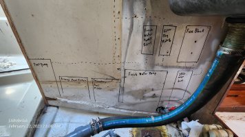
First draft/Rough layout of new design, concentrating on accessibility for maintenance -

20230222_110639.jpg

1/4 berth wall will be utilized for hose, wire and cable routing.

Side note - why is there a shut off on the ice box drain?
 

Loren Beach

O34 - Portland, OR
Senior Moderator
Blogs Author
Side note - why is there a shut off on the ice box drain?
That's an easy question. (!) :)
Cold air sinks and it steadily runs out of the ice box, depleting your ice and adjacent 32 degree water in the bottom even faster. The alternative is to have an open drain hose to your bilge so that the ice box will not accumulate slimy water. (Said water and detritus will then grow slimy things in your bilge... not really an improvement.)

Our boat came with an open hose outlet to the bilge, so I promptly put a little quarter turn plastic valve on the end of it. Then, a few years later I installed a 12 volt refrigeration system. Great Happiness ensued, and continues into a further decade.

So a prior owner must have put valve there, is my SWAG.

Back to your drawn up lay out, be careful to allow enough room for attachments and plumbing fittings for those parts. Notice pix 3, 4, and 5, in my blog entry. These connecting bits can take up more room than one imagines when in the design phase. https://ericsonyachts.org/ie/ubs/new-location-racor-lift-pump.682/
 
Last edited:

Nick J

Sustaining Member
Moderator
Blogs Author
After much consideration, I went the other direction. I removed the waste basket. Probably will put a removable half waste basket in place.

First draft/Rough layout of new design, concentrating on accessibility for maintenance -

View attachment 46075

1/4 berth wall will be utilized for hose, wire and cable routing.

Side note - why is there a shut off on the ice box drain?
What's the purpose for the fresh water relay? I've been thinking about using a few relays to remove the circuit length required to have switches in easily accessible locations. I hadn't thought about using one in the fresh water system because the pressure switch is located on the pump.
 

Dave G.

1984 E30+ Ludington, MI
Side note - why is there a shut off on the ice box drain?
I disconnected the thru-hull "drain" from my icebox. The bottom of the icebox is very close to the water line which meant you could only drain the icebox under sail on a port tack or you would have seawater infiltrating even at the dock with minimal wave action. I installed a hand pump on the galley counter and ran the drain hose to it. Much more manageable and sanitary.
 

Alan Gomes

Sustaining Partner
I disconnected the thru-hull "drain" from my icebox. The bottom of the icebox is very close to the water line which meant you could only drain the icebox under sail on a port tack or you would have seawater infiltrating even at the dock with minimal wave action. I installed a hand pump on the galley counter and ran the drain hose to it. Much more manageable and sanitary.
I did something similar, except that I used a ShurFlo electric pump to do the deed.
 

Jaybee

Cocoa, FL 1984 30+
That's an easy question. (!) :)
Cold air sinks and it steadily runs out of the ice box, depleting your ice and adjacent 32 degree water in the bottom even faster. The alternative is to have an open drain hose to your bilge so that the ice box will not accumulate slimy water. (Said water and detritus will then grow slimy things in your bilge... not really an improvement.)

Our boat came with an open hose outlet to the bilge, so I promptly put a little quarter turn plastic valve on the end of it. Then, a few years later I installed a 12 volt refrigeration system. Great Happiness ensued, and continues into a further decade.

So a prior owner must have put valve there, is my SWAG.

Back to your drawn up lay out, be careful to allow enough room for attachments and plumbing fittings for those parts. Notice pix 3, 4, and 5, in my blog entry. These connecting bits can take up more room than one imagines when in the design phase. https://ericsonyachts.org/ie/ubs/new-location-racor-lift-pump.682/

ah, I was focused on the liquid and not the invisible fluid, makes sense to me.
 

Jaybee

Cocoa, FL 1984 30+
What's the purpose for the fresh water relay? I've been thinking about using a few relays to remove the circuit length required to have switches in easily accessible locations. I hadn't thought about using one in the fresh water system because the pressure switch is located on the pump.

Probably not necessary at all for this application and might not make it to V2.0 but for the glow plug example just so I can run a lower amperage through the switch and therefore keeping higher dollar higher amperage wiring runs shorter. Using smaller wire for longer runs arguably reduces fire risk, reduces wear on switch contacts and saves a few coins though not a whole lot in a 30 foot boat. A few more points could be made but for me also, performance, voltage drop through wiring reduces performance so a shorter run should theoretically produce better performance as well (though you can upgauge the wiring to maintain that performance but then the aforementioned cons).
 

Dave G.

1984 E30+ Ludington, MI
First draft/Rough layout of new design
I would agree with Loren that "plumbing" all that together will require more spacing ? Also I'm guessing that is the port side of the engine bay ? Access to that area may be iffy with engine in place. Mine has alternator and starter on that side so not much room. Without the waste basket maybe better(I like the idea & will explore that option myself I think) but then you have to access that from the aft which is tight too and involves contorting into position.
 

Jaybee

Cocoa, FL 1984 30+
I would agree with Loren that "plumbing" all that together will require more spacing ? Also I'm guessing that is the port side of the engine bay ? Access to that area may be iffy with engine in place. Mine has alternator and starter on that side so not much room. Without the waste basket maybe better(I like the idea & will explore that option myself I think) but then you have to access that from the aft which is tight too and involves contorting into position.

Yes, port engine bay - engine is currently in place.

The boxes I drew were extra generous, but I will probably have to shuffle things just a bit.

The most likely thing to be accessed is the fuse box, which is readily accessible. (certainly way more so than the A/C panel that was previously down there...)

With the waste basket out the new filter location is easy to access. I'm still deliberating a few things, I probably will only have one filter after the pump in the final design as the fuel pump has an 80-micron cleanable filter built into it which gives me more room for plumbing.
 
Top