Mast Step Wiring Conduit 35-2?

WindHorse

Member I
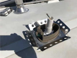
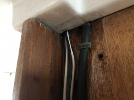
Forgive me if the answer is already on the forum somewhere else, but I couldn’t find it... I seem to have a short in my VHF coaxial within the mast—my best guess is that it’s at/near the connection at the base. So, what would otherwise be a simple and relatively inexpensive repair is going to cost quite a bit of time and money to haul out, unstep the mast, and deal with this. While I’m at it, I might as well modify the wiring transition from the mast to the cabin such that all connections are below deck and I have a utility line in place to pull new wiring in the future (e.g., installing/maintaining mast head instruments). Thus, I need to figure out a conduit system that allows for running the wiring through the step without it being pinched or obstructed. Currently, the existing wires and coaxial are completely fixed. In order to plan ahead with feasible materials, can anyone tell me what the deck side of the photo looks like on a model near me (1970, E35-2, #155)???

short of drilling a hole at the base of my mast, I have no way to inspect from the top, as everything is fixed with rivets...

thank
 

Attachments

  • 012AF78A-08B1-46B9-8BF7-E9C39017B841.jpeg
    012AF78A-08B1-46B9-8BF7-E9C39017B841.jpeg
    129.8 KB · Views: 16

kapnkd

kapnkd
Your ‘70 E-35 should be similar/identical to our ‘73 E-32 other than a slightly larger mast and base plate.

The plate has a flat bottom to rest on the cabin top and holes for wires to pass through. There’s also a drainage grove in it for trapped water to run out. (Note that we enlarged our grove for better drainage when we removed our base.)
CBD373FE-2B03-4EEA-8A89-8F6E0BC4BBE4.jpeg
0B2609C3-1603-4FEC-A440-9CCF3089DEBF.jpeg

Your thoughts of having all connections inside the cabin aren’t advisable/recommended as if/when you need to remove the mast at a later point in time, you’ll need to cut your connectors to pass the wires back up through the deck and mast plate. When you pull your mast, there should be connectors already installed. No doubt you will want to replace them all “While you are at it”. Just allow ample excess wiring for when the mast is first raised off the deck to access your connectors to be uncoupled. (Be sure to create a “gooseneck” of sorts in the wires to prevent water following down the wires from going straight down and into your cabin.)

We also put in a short pvc tube on/into the base plate sealing the outer edges to prevent water sitting on the plate from also running into the cabin.

Not sure how far you’re going to pursue your project but “While we are at it” kicked in and we added a SS halyard organizer under the base to allow for leading lines back to the cockpit.
19C487E8-4E1B-4A54-BDB5-57D5D1006E1A.jpeg
We created a tech drawing for Garhauer which was done to perfection.

Shaffing or tangling of electrical wires was addressed by adding a long piece of pvc tubing to keep them restricted and from wanting to dance with our internal halyards. (The real trick was securing the pvc so it too didn’t clunk around in the mast!)

Hope this helps! ...Fair Winds!
 

Loren Beach

O34 - Portland, OR
Senior Moderator
Blogs Author
One of the 'best things' about this site is spotting good ideas and details while studying nearby semi-related solutions. That nice ss halyard block plate looks like a stronger version of the Kenyon one on our boat. (Previously I had added a similar plate with 'wings' to our prior N-26.)
And, another well deserved shoutout for Garhauer. :)
Thanks for the narrative and photos!
 

kapnkd

kapnkd
One of the 'best things' about this site is spotting good ideas and details while studying nearby semi-related solutions. That nice ss halyard block plate looks like a stronger version of the Kenyon one on our boat. (Previously I had added a similar plate with 'wings' to our prior N-26.)
And, another well deserved shoutout for Garhauer. :)
Thanks for the narrative and photos!

Thanks for the compliment Loren ...and yes, Garhauer has a tendency to always exceed expectations! It arrived with such a highly polished (like chrome) surface that we felt bad covering it up with the mast.

Think I saved the technical illustration for the plate, should anyone want it. I can probably turn it into a PDF file easily enough.
 

bigd14

Contributing Partner
Blogs Author
Here is a photo of the PVC standpipe method that kapnkd mentioned (different boat but same concept). A drip loop in the wire bundle diverts water from the pipe. When I had the mast step off, I enlarged the hole through the deck and the step to fit more wires and aligned them better. I can't remember if I soaked the exposed wood with epoxy, but I should have. At any rate no noticeable moisture has come through the deck with the standpipe arrangement and the wires slide easily through.

As for using a tagline from masthead to cabin to install new instrument cabling without unstepping the mast I think it would be difficult. Too many sharp turns, protruding screws, halyards, other wire etc. in the way. I would be worried about damaging any new cable I tried to pull through or getting it stuck. Perhaps its possible with careful thought, alignment and execution though.

For connector location, I'll offer a counterpoint to kapnkd. I have used both the in-mast connection and the in-cabin connection methods and I prefer the in-cabin method. I have a busbar on the underside of the cabin and make all the connections inside. I leave the mast wires extra long and just cut the connectors off when unstepping. When stepping the mast, I can pull the bare wire bundle through easily with a tagline. This allows the mast to be placed onto the step quickly without having it swinging precariously over the boat while connections are made. Less crane costs and I can make the connections leisurely from inside once the mast is up. And if you cross some wires by accident you can fix them! The connectors are a bit more protected from the elements and can be replaced if they fail without removing the mast. This may not be ideal if you step and unstep the mast every year though as eventually you may run out of wire.

Good luck with the project.
 

Attachments

  • Picture1.png
    Picture1.png
    811.4 KB · Views: 26

kapnkd

kapnkd
Here is a photo of the PVC standpipe method that kapnkd mentioned (different boat but same concept). A drip loop in the wire bundle diverts water from the pipe. When I had the mast step off, I enlarged the hole through the deck and the step to fit more wires and aligned them better. I can't remember if I soaked the exposed wood with epoxy, but I should have. At any rate no noticeable moisture has come through the deck with the standpipe arrangement and the wires slide easily through.

As for using a tagline from masthead to cabin to install new instrument cabling without unstepping the mast I think it would be difficult. Too many sharp turns, protruding screws, halyards, other wire etc. in the way. I would be worried about damaging any new cable I tried to pull through or getting it stuck. Perhaps its possible with careful thought, alignment and execution though.

For connector location, I'll offer a counterpoint to kapnkd. I have used both the in-mast connection and the in-cabin connection methods and I prefer the in-cabin method. I have a busbar on the underside of the cabin and make all the connections inside. I leave the mast wires extra long and just cut the connectors off when unstepping. When stepping the mast, I can pull the bare wire bundle through easily with a tagline. This allows the mast to be placed onto the step quickly without having it swinging precariously over the boat while connections are made. Less crane costs and I can make the connections leisurely from inside once the mast is up. And if you cross some wires by accident you can fix them! The connectors are a bit more protected from the elements and can be replaced if they fail without removing the mast. This may not be ideal if you step and unstep the mast every year though as eventually you may run out of wire.

Good luck with the project.

Excellent options! ...Since we step and unstep our mast seasonally, we prefer the above deck method. At least now there are more options for consideration.
 

WindHorse

Member I
Your ‘70 E-35 should be similar/identical to our ‘73 E-32 other than a slightly larger mast and base plate.

The plate has a flat bottom to rest on the cabin top and holes for wires to pass through. There’s also a drainage grove in it for trapped water to run out. (Note that we enlarged our grove for better drainage when we removed our base.)
View attachment 38816
View attachment 38817

Your thoughts of having all connections inside the cabin aren’t advisable/recommended as if/when you need to remove the mast at a later point in time, you’ll need to cut your connectors to pass the wires back up through the deck and mast plate. When you pull your mast, there should be connectors already installed. No doubt you will want to replace them all “While you are at it”. Just allow ample excess wiring for when the mast is first raised off the deck to access your connectors to be uncoupled. (Be sure to create a “gooseneck” of sorts in the wires to prevent water following down the wires from going straight down and into your cabin.)

We also put in a short pvc tube on/into the base plate sealing the outer edges to prevent water sitting on the plate from also running into the cabin.

Not sure how far you’re going to pursue your project but “While we are at it” kicked in and we added a SS halyard organizer under the base to allow for leading lines back to the cockpit.
View attachment 38818
We created a tech drawing for Garhauer which was done to perfection.

Shaffing or tangling of electrical wires was addressed by adding a long piece of pvc tubing to keep them restricted and from wanting to dance with our internal halyards. (The real trick was securing the pvc so it too didn’t clunk around in the mast!)

Hope this helps! ...Fair Winds!
Thanks for the detailed reply! Yes, I'm mindful of needing to cut the wires to unstep in the future, but I'd much rather deal with that then to wonder about failing connections on the inside of the mast and have to unstep just to fix a connection (like I am, now!). For the coaxial, I'd also like to just run one continuous line all the way to the radio (and I don't mind feeding it all back out in the event of unstepping. I'm thinking that an oversized 135-degree conduit cap might be enough to force the "gooseneck" dripline while also allowing wires to pull. I'll probably make a mock-up to test it once I know the parameters I'm dealing with. Also, my mast is only a few years old, already has the SS halyard organizer at the base, and has a conduit inside to separate the wiring from the halyards. If only the PO had ensure the coaxial connection was solid! In any case, I'd like to run new wiring for wind and camera, so...
 

WindHorse

Member I
Here is a photo of the PVC standpipe method that kapnkd mentioned (different boat but same concept). A drip loop in the wire bundle diverts water from the pipe. When I had the mast step off, I enlarged the hole through the deck and the step to fit more wires and aligned them better. I can't remember if I soaked the exposed wood with epoxy, but I should have. At any rate no noticeable moisture has come through the deck with the standpipe arrangement and the wires slide easily through.

As for using a tagline from masthead to cabin to install new instrument cabling without unstepping the mast I think it would be difficult. Too many sharp turns, protruding screws, halyards, other wire etc. in the way. I would be worried about damaging any new cable I tried to pull through or getting it stuck. Perhaps its possible with careful thought, alignment and execution though.

For connector location, I'll offer a counterpoint to kapnkd. I have used both the in-mast connection and the in-cabin connection methods and I prefer the in-cabin method. I have a busbar on the underside of the cabin and make all the connections inside. I leave the mast wires extra long and just cut the connectors off when unstepping. When stepping the mast, I can pull the bare wire bundle through easily with a tagline. This allows the mast to be placed onto the step quickly without having it swinging precariously over the boat while connections are made. Less crane costs and I can make the connections leisurely from inside once the mast is up. And if you cross some wires by accident you can fix them! The connectors are a bit more protected from the elements and can be replaced if they fail without removing the mast. This may not be ideal if you step and unstep the mast every year though as eventually you may run out of wire.

Good luck with the project.
Thanks for the input, bigd14! It looks like we have similar rationale--and, now, I don't plan on unstepping again anytime soon--and certainly not seasonally. Question: How do you create a dripline after pulling the wires? Or, do you bend the wire during stepping? Also, what about your VHF coaxial? Is it within the same bundle?
 

bigd14

Contributing Partner
Blogs Author
For the drip loop before stepping the mast, I just created a 180 degree bend (not too tight) in the entire mast wiring bundle including coaxial. The bottom of the bend was about 1 inch up from the bottom of the mast and I put a ziptie around the entire bundle to hold the bend in place. As the mast was lowered into place I just gently pulled the bitter end of the wire bundle through from below taking up slack but not pulling too hard so as to crimp the coaxial or pull the drip loop out. So the drip loop is kind of an "N" shape in its final position inside the mast. So far so good 3 years later and no visible water intrusion. Make sure you test whether you can pull a bundle of wires the same size that the actual mast wiring and coaxial bundle will be!
 

KS Dave

Dastardly Villain
Blogs Author
Here is a photo of the PVC standpipe method that kapnkd mentioned (different boat but same concept). A drip loop in the wire bundle diverts water from the pipe. When I had the mast step off, I enlarged the hole through the deck and the step to fit more wires and aligned them better. I can't remember if I soaked the exposed wood with epoxy, but I should have. At any rate no noticeable moisture has come through the deck with the standpipe arrangement and the wires slide easily through.

The E26-2 has a deck-stepped mast, as well, and a mast pull is a bigger ordeal where I live. My wiring is all suspect and I intend to replace it. I was weighing cutting an access plate to allow me to troubleshoot the connector in the future (the weak point in the whole system), but this seems idea like a better option. A few questions, if I may?
  1. How far down does the PVC pipe go into the cabin? Any bends once there?
  2. What product did you use to seal the pipe in place?
  3. Do you have any pictures of what this looks like inside the cabin?
  4. Does this come out in the ceiling of the head? Or where on the E30?
  5. Why do you have to cut the wires if you remove it? If they are terminated on a strip, couldn't you just undo those and pull it back through with the connectors intact?
 
Last edited:

bigd14

Contributing Partner
Blogs Author
Hi Dave-

1. The PVC pipe only goes to the bottom of the mast step plate and sits over the hole through the deck. I had to remove sealant from this junction when I gooped up the bottom of the mast plate so it didn't harden and make the hole narrower.
2. I used Sikaflex 291, but any marine caulk would work (without silicone of course!)
3. Sorry I don't have any pictures but it looks very similar to the picture in Post 1
4. The wire bundle comes out into the the head compartment by the mast support post , see Post 1 pic again
5. The hole running through the deck and partway through a bit of the mast support is small. I drilled it out some but its a very tight fit for the wire bundle. Even if I staggered the end fittings they would still jam, so it was easier to leave a few feet of extra wire and cable and just clip the fittings off when the time comes to unstep the mast. If you can enlarge the hole enough to pass wires freely you could leave the end fittings on. This might require a larger standpipe to cover the hole however. The extra wire is just tucked into the headliner.

My goal was to make it super easy to prepare the boat for the yard to install or remove the mast (less $$). I had a nasty experience with the mast and step when we first got the boat. The step had corroded to the mast and the mast would not come off the boat. The entire boat started coming out of the water when they started lifting the mast off! The three wood screws holding the step to the boat were subjected to enormous pressure and I was lucky nothing broke. It took about 30 minutes of me bashing and wedging the step off the mast while the Travel Lift held it and the clock ticked away burning $$ on the operator and the other two crew working the removal. I vowed that future mast removals would be simplified as much as possible.
 

KS Dave

Dastardly Villain
Blogs Author
Ah-ha! I totally overlooked the first picture. Thanks for taking time to type out answers to all my questions; very helpful in helping me form a plan. I have no idea what kind of experience removing the mast is going to be. I'm pretty sure it's been off in the last 20 years, but not sure; hopefully it won't be frozen in place. After I posted this, I found another thread from @toddster that shows a similar inside picture. It appears he enlarged and modified it a bit.

I've dug around up in the ceiling a bit, but I haven't located the actual hole where the wires come through. I'll keep investigating. Appreciate the help!
 
Top