davisr
Member III
In the month since I have purchased my E25, cb, I have been removing deck hardware for rebedding and have been reworking the centerboard. Concurrently, I have been doing research for some other needed upgrades, one of which concerns the wiring. I have been reading Don Casey's two books, This Old Boat and the Sailboat Maintenance Manual. Both are very helpful. Casey stresses, as do others on this Forum, that it is important to use Type 3 tinned copper wiring. He, and others, have also said that it imperative to use crimped terminals, both for joining wires and for connecting wires to electrical panels.
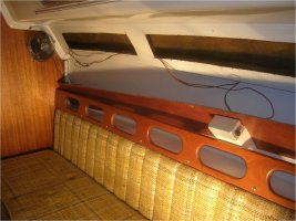
I have two questions, both of which concern the joining of fixtures such as lights and fans in a circuit. Currently, all five house lights (and one fan) are joined in a series circuit. The wire appears to be 16 gauge, Type 2, untinned wire. Each light contains one, #1141, 18 watt incandescent bulb. These lights work sometimes . . . but not all the time. The wire appears to be original. The lights certainly are. I believe the problem is this: the wire is old and the fixtures are joined in a loose fashion (see pictures below). I plan to replace this wire and replace the existing lights with LEDs for the purpose of saving battery power.
Here are my questions:
1. Don Casey emphatically says that one should never wire fixtures in a series, but rather in a parallel circuit. The parallel circuit reduces the resistance that would otherwise be multiplied in the series circuit. What is everyone's experience with these types of circuits on a sailboat, especially in terms of LED fixtures? A parallel circuit would seem to require two or three times the amount of wire, especially since the wires run around the perimeter of the interior of the boat.
2. When joining light fixtures to the positive and negative wires in the circuit, how would you suggest that I make the connections? In a house, of course, one would use a junction box for AC connections. Don Casey does not offer an explanation (at least one that I have found) for this procedure on a sailboat when it comes to DC. One of the pictures below shows the method used during the production process.
Explanation of Images
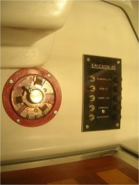
001: Starboard Main Salon House Light, where the circuit begins, then connects with Fan before passing behind bulkhead into Head
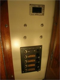
002: Head with its House Light connected to circuit
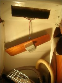
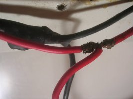
003: Detail of House Light in Head with bare-wire wrapped connection (with electrical tape removed)
Many thanks Forum members for any help you may offer with this,
Roscoe
E25, cb, Hull 226
I have two questions, both of which concern the joining of fixtures such as lights and fans in a circuit. Currently, all five house lights (and one fan) are joined in a series circuit. The wire appears to be 16 gauge, Type 2, untinned wire. Each light contains one, #1141, 18 watt incandescent bulb. These lights work sometimes . . . but not all the time. The wire appears to be original. The lights certainly are. I believe the problem is this: the wire is old and the fixtures are joined in a loose fashion (see pictures below). I plan to replace this wire and replace the existing lights with LEDs for the purpose of saving battery power.
Here are my questions:
1. Don Casey emphatically says that one should never wire fixtures in a series, but rather in a parallel circuit. The parallel circuit reduces the resistance that would otherwise be multiplied in the series circuit. What is everyone's experience with these types of circuits on a sailboat, especially in terms of LED fixtures? A parallel circuit would seem to require two or three times the amount of wire, especially since the wires run around the perimeter of the interior of the boat.
2. When joining light fixtures to the positive and negative wires in the circuit, how would you suggest that I make the connections? In a house, of course, one would use a junction box for AC connections. Don Casey does not offer an explanation (at least one that I have found) for this procedure on a sailboat when it comes to DC. One of the pictures below shows the method used during the production process.
Explanation of Images
001: Starboard Main Salon House Light, where the circuit begins, then connects with Fan before passing behind bulkhead into Head
002: Head with its House Light connected to circuit
003: Detail of House Light in Head with bare-wire wrapped connection (with electrical tape removed)
Many thanks Forum members for any help you may offer with this,
Roscoe
E25, cb, Hull 226
Attachments
-
 E25ElectricPix001.jpg95 KB · Views: 64
 -
 E25ElectricPix002.jpg41 KB · Views: 95
 -
 E25ElectricPix003.jpg45.9 KB · Views: 91
 ffice
ffice ></o
></o