You are using an out of date browser. It may not display this or other websites correctly.
You should upgrade or use an alternative browser.
You should upgrade or use an alternative browser.
E25+ diesel install
- Thread starter DEUII
- Start date
unequaltee
Member II
Engine install
Hi,
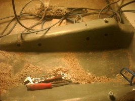
I don’t know if its any help to you at all, but here are some pictures of the engine install that I did on my E 35-2 .(moved from a centre location to under the companionway) I shouldthink the principles much the same. I will add - while I have fitted a fewengines this was the first complete install, and, I enjoyed all of it, exept maybe the cutting of the holes in the bottom of the hull!!
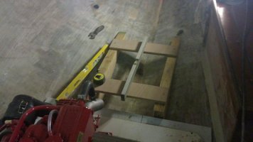
I used a piece of metal 3/8 rod fed through the old cockpit drain hole to get the rough angle for the shaft. I had to bend it like a flat top hat , using the brim of the “hat” in line to the engine bearers and shaft position outside.
I used a laser level off the engine bearers to mark the hole for the shaft hole (the red dot is just visible in the top of the picture)
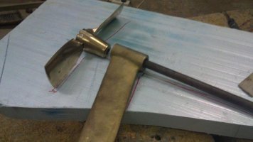
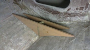
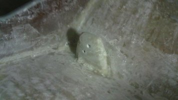
To line up the log/stern tube and P bracket, I used a length of 1 inch bright steel bar slid right through and up the middle of the bearers. For the front of the stern tube I used a ½ “ thick piece of plastic , cut to the size of the tube and drilled to fit the shaft . The P bracket and stern tube had 25mm cutlass bearings so the 1” was a nice tight fit to keep it all in line while the epoxy set .
The stern tube I used was a Vetus 500mm fibreglass tube cut to length.
I hope this makes some sort of sense. I had some help with getting the shaft in somewhere near the factory position from other members kindly supplying some photographs. I don’t know if this is an option for the E25.
Good luck
Ian
Hi,
I don’t know if its any help to you at all, but here are some pictures of the engine install that I did on my E 35-2 .(moved from a centre location to under the companionway) I shouldthink the principles much the same. I will add - while I have fitted a fewengines this was the first complete install, and, I enjoyed all of it, exept maybe the cutting of the holes in the bottom of the hull!!
I used a piece of metal 3/8 rod fed through the old cockpit drain hole to get the rough angle for the shaft. I had to bend it like a flat top hat , using the brim of the “hat” in line to the engine bearers and shaft position outside.
I used a laser level off the engine bearers to mark the hole for the shaft hole (the red dot is just visible in the top of the picture)
To line up the log/stern tube and P bracket, I used a length of 1 inch bright steel bar slid right through and up the middle of the bearers. For the front of the stern tube I used a ½ “ thick piece of plastic , cut to the size of the tube and drilled to fit the shaft . The P bracket and stern tube had 25mm cutlass bearings so the 1” was a nice tight fit to keep it all in line while the epoxy set .
The stern tube I used was a Vetus 500mm fibreglass tube cut to length.
I hope this makes some sort of sense. I had some help with getting the shaft in somewhere near the factory position from other members kindly supplying some photographs. I don’t know if this is an option for the E25.
Good luck
Ian
Attachments
-
 setting bearers (2).jpg53.5 KB · Views: 50
 -
 p bracket (2).jpg51.8 KB · Views: 68
 -
 27102010104.jpg56.8 KB · Views: 65
 -
 P bracket interior (2).jpg49.4 KB · Views: 51
 -
 Engine bed (2).jpg101.5 KB · Views: 65
unequaltee
Member II
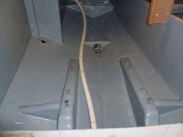
The finished Job
only allowed a max of 5 pics so here is the finished job.
only allowed a max of 5 pics so here is the finished job.
Attachments
-
 engine bay.jpg57.2 KB · Views: 162
Wow!
VERY impressive work. Way beyond anything I have ever attempted.
Was this a move in location from the original inboard engine location?? And, what was the motivation?
Loren
VERY impressive work. Way beyond anything I have ever attempted.
Was this a move in location from the original inboard engine location?? And, what was the motivation?
Loren
unequaltee
Member II
Engine move
Was this a move in location from the original inboard engine location?? And, what was the motivation?
Yes Loren, this was indeed a move from the central location.
As for the reason ,there was a few. The original mounts had totally rusted away , a new diesel, the ¾” shaft. Most of the interior ply from the fore cabin aft had delaminated so I ended up with a blank canvas to re- build the boat how I wanted , and that was for cruising. ( Although I do like to cruise in a boat that sails well, which, as well as her beautiful lines was the reason for buying the boat in the fist place) But I was prepared to forego a little performance for more room in the cabin. I will post some pictures of the re-designed interior when further along.
Ian
Ian, thank you for the reply. Very helpful. I'm in the process of gathering all my materials. Hopefully by spring I can start work when the weather warms up. Once again, thanks for the photos and the info on the stern tube.
Don
Don
Hi,
I don’t know if its any help to you at all, but here are some pictures of the engine install that I did on my E 35-2 .(moved from a centre location to under the companionway) I shouldthink the principles much the same. I will add - while I have fitted a fewengines this was the first complete install, and, I enjoyed all of it, exept maybe the cutting of the holes in the bottom of the hull!!
I used a piece of metal 3/8 rod fed through the old cockpit drain hole to get the rough angle for the shaft. I had to bend it like a flat top hat , using the brim of the “hat” in line to the engine bearers and shaft position outside.
I used a laser level off the engine bearers to mark the hole for the shaft hole (the red dot is just visible in the top of the picture)
To line up the log/stern tube and P bracket, I used a length of 1 inch bright steel bar slid right through and up the middle of the bearers. For the front of the stern tube I used a ½ “ thick piece of plastic , cut to the size of the tube and drilled to fit the shaft . The P bracket and stern tube had 25mm cutlass bearings so the 1” was a nice tight fit to keep it all in line while the epoxy set .
The stern tube I used was a Vetus 500mm fibreglass tube cut to length.
I hope this makes some sort of sense. I had some help with getting the shaft in somewhere near the factory position from other members kindly supplying some photographs. I don’t know if this is an option for the E25.
Good luck
Ian