Deep cycle or dual purpose batteries?

Kenneth K

1985 32-3, Puget Sound
Blogs Author
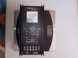
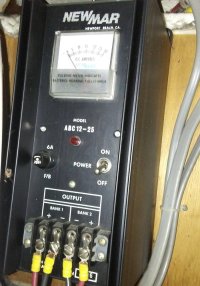
This is my old charger. Almost as bad as Christian's.

20160905_193410.jpg 20201121_134840.jpg

It was installed way up in the upper forward coaming area behind the galley/tilt-out dish holder. Not only was this a horrible place to access for service, but it was hot (in the summer), poorly ventilated, and the long distance to the battery box left about a 16ft cable run to the DC panel. The long run of 10ga wire left the batteries chronically undercharged--whatever voltage the charger put out, the batteries were receiving several tenths less due to voltage drop.

When I put in a new charger, I put it under the nav table--about 2 ft away from the main battery box. Details here: https://ericsonyachts.org/ie/ubs/battery-systems-upgrade.921/ Nothing fancy on the batteries though. I'm a flooded-lead-acid guy (Costco/Interstate 80A-hr FLA deep cycle). Last pair was about was about $80 a piece, and they seem to last 7-8 years.
 
Last edited:

G Kiba

Sustaining Member
My charger supports both lead acid and AGMs with a setting change (dip switches). I updated to the twice-as-expensive AGMs hoping to avoid the maintenance of filling the cells with water and maybe not buying replacements as soon. Venting was also a concern as the batteries are in a settee compartment separated from the cushion by a 1/4" thick cover with an access hole in it. Batteries are going on 3 years now without issue charging to 12.8V down from 13.2V when new. So far, so good?
 

bsangs

E35-3 - New Jersey
To be clear, my "old" charger is nothing like those relics, gentlemen. It's a Promariner Prosport20. Has many different charging profiles, conditions the batteries, etc. It's from 2011 or so - modern enough. Though I assure you, there's no "attachment" to it. :D
 

bsangs

E35-3 - New Jersey
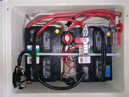
I have often wondered about this. I do sometimes get a whiff of battery charging gas (two lead acid golf cart batteries). Thousands of boats must have similar arrangements and I don’t hear about too many of them spontaneously combusting from it, so I have chosen not to worry about it. I figure the lid and the old wiring holes and the generally porous nature of the aft end of the boat is enough to keep the gas from concentrating too much. Unfortunately though, there is a ton of wiring right next to the batteries, but it’s new wiring, so I just hope for no sparkiness.


View attachment 49157
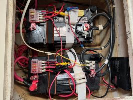
Here, allow me to ease your concerns about your "ton of wiring right next to the batteries." :D And this is cleaned up dramatically from when I first purchased her. I'm insanely jealous of your neat and tidy battery box. When I put in my new batteries, I plan to clean this up better. Oh, I never smell any battery charging gas. These batteries require no maintenance, and are strapped down beneath the aft small seat of the port side settee.

IMG_0687 (1).jpeg
 

bsangs

E35-3 - New Jersey
Why the inline fuses on wires that already come off a fuse block?
Those fuse blocks didn’t exist when I got the boat. Everything was running directly to the battery posts. Needless to say, that was not kosher, so I added the fuse blocks, but didn’t change the wiring. Planning to get to it eventually, but am still learning the boat electrical world.
 

Alan Gomes

Sustaining Partner
Kinda late to the party here, but I just got discharged from the hospital after a major surgery on Wednesday. I've been following this particular thread with interest (from my hospital bed) because I just recently installed a new Sterling 30A charger and wanted to weigh in with a few thoughts. But typing on an iPhone is purgatory, so I figured I'd hold off until I got back to a computer.

First, I highly recommend this article by MaineSail that's full of good information on chargers, battery charging protocols, and so forth.

One of the (several) main takeaways from this article is that a key to charging batteries properly is to select the correct voltages for the absorption and float stages. And the best way to do that is: (1) to find out the correct voltages from the battery manufacturer, as this can and does vary from battery to battery, even for the same battery type; and (2) to use a charger that lets you set these manually in case one of the charger's presets does not exactly fit the bill. (Alternatively, I suppose you could always buy your batteries around what presets your charger furnishes.)

The flip side of the above advice is that selecting a charging protocol based on, e.g., pre-defined dipswitch settings frequently will not yield the result you want. He stresses repeatedly that you want to set your charger based on the required voltages and not whatever labels your charger may give to any particular setting. So, for example, if your charger had an AGM setting that happened to correspond to the voltages that your particular flooded battery wanted to see, you'd select it regardless of the label not matching.

My flooded Group 24s, now and in the past, were not giving me good service, being chronically undercharged by my wimpy little Guest charger. I just installed the Sterling ProCharge Ultra 1230--plenty of charger for my needs. This charger is highly recommended in MaineSail's article, and I especially liked the fact that I could dial in the exact voltages I wanted if none of the presets sufficed. I also liked that it has a setting to desulphate the batteries. My particular 3 year-old batteries were not in great shape due to the chronic undercharging, but I thought that by equalizing them I might be able to breathe a bit of life back into them and nurse them along for a little while longer before replacement. Then, with a fresh set of batteries, the new charger should maintain them properly moving forward. Or so I hope.

My batteries are from Sam's Club and are 75 Ah Group 24 deep cycle Marine batteries. I have two of them, jumpered to be in parallel and present as one larger battery. They are branded as Duracell but are manufactured by East Penn. I contacted East Penn and they sent me the data sheet that gives the charging parameters, which I've attached. Again, the numbers I am after are for the absorption and float stages. These are expressed as a range. So for the absorption stage I can set the charger between 14.4 and 14.7V, while the float charge for these batteries can be set from 13.8 to 14.1V. After contacting Sterling tech support to get their take on it, we settled on an absorption setting of 14.6 and a float of 13.8. Note that the charger's temperature compensation will bump these numbers up or down a bit depending on the battery temperature, but these are the baseline numbers.

Since none of the presets exactly matched these numbers, I simply dialed them in using a custom profile.

After installing the charger I ran one desulphation cycle on these batteries. I then let the charger maintain them according to my custom profile.

It's a bit hard to say whether this charger will breath some new life back into these abused batteries, especially since I don't have any battery monitor to measure the capacity with any real precision. I did spend two days on the boat with the charger turned off and running normal house loads to see how the batteries were performing. Roughly speaking, they seemed to be holding a better charge than before. This was based on running what I usually run: lights, laptop, iPad, CPAP machine at night, and so forth. But as I say, I really can't quantify it with any precision.

I'm planning to swap out these batteries in the next few months in any event, most likely with a couple of new Duracells also from Sam's. The real test will be how these new batteries hold up with the new charger.
 

Attachments

  • Renewable Energy Charging Parameters (from East Penn).pdf
    69.5 KB · Views: 3

Kenneth K

1985 32-3, Puget Sound
Blogs Author
Alan,

+1 on the Sterling Ultra 1230 charger.

If you're checking the charging profiles so closely, I'd also use a voltmeter to check the actual charge voltage received at the battery posts. This will equal the charger output voltage minus the voltage drop in the lines. My factory install (long runs of 10 ga wires) meant my batteries were receiving several tenths less voltage than the charger put out.

My Victron solar setup uses a blue-tooth sensor that mounts to the main battery bank. It gives feedback to the charge controller of the actual voltage and temperature at the battery bank. The charge controller then adjust output to keep the proper charge at the battery. The 1230 uses a temperature sensor, but gets no feedback on voltage.
 

southofvictor

Member III
Blogs Author
If you're checking the charging profiles so closely, I'd also use a voltmeter to check the actual charge voltage received at the battery posts. This will equal the charger output voltage minus the voltage drop in the lines.
Very good idea, especially if there are bus bars and splitters between the charger and the batteries. Old style diode splitters especially as they usually have a big voltage drop through them and are a frequent contributor to chronic undercharging.
 

Alan Gomes

Sustaining Partner
Alan,

+1 on the Sterling Ultra 1230 charger.

If you're checking the charging profiles so closely, I'd also use a voltmeter to check the actual charge voltage received at the battery posts. This will equal the charger output voltage minus the voltage drop in the lines. My factory install (long runs of 10 ga wires) meant my batteries were receiving several tenths less voltage than the charger put out.

My Victron solar setup uses a blue-tooth sensor that mounts to the main battery bank. It gives feedback to the charge controller of the actual voltage and temperature at the battery bank. The charge controller then adjust output to keep the proper charge at the battery. The 1230 uses a temperature sensor, but gets no feedback on voltage.
Good points, Ken.

I have the charger located close to my batteries: about a 5' run. I sized the cable at 10AWG, which is conservative. (The Sterling documentation says I could have used 12AWG for a 5' length and recommends 10AWG for a 10' run.)

I attempted to measure the voltage at the battery terminals only to discover that my cheapie VOM went belly-up. I have a panel meter that is showing approximately the correct voltage, but I know that is not a proper substitute for measuring it directly at the battery terminals. Before I went into the hospital I ordered a new Fluke meter that's I've got sitting here and will use to check out the measurements at the battery, once I've healed up enough to be able to drive and start climbing around on my boat again, maybe in a week or so, give or take. At this point, though, I have no real reason to think anything is amiss. But I will check it out just to be sure.
 

Alan Gomes

Sustaining Partner
Very good idea, especially if there are bus bars and splitters between the charger and the batteries. Old style diode splitters especially as they usually have a big voltage drop through them and are a frequent contributor to chronic undercharging.
Again, a good point. In my case, I have the wires running directly from the charger and straight to the battery terminals. (There is a 40A fuse for the charger on the positive terminal.)
 

Kenneth K

1985 32-3, Puget Sound
Blogs Author
Here, allow me to ease your concerns about your "ton of wiring right next to the batteries." :D And this is cleaned up dramatically from when I first purchased her.
I'm a fan of the battery-top fuse terminals too. I have two in my battery box. One is located remotely on the sidewall, powered by an a 8ga feeder wire. That one is "switched" so it's not always "hot." This setup was a "shortcut" compared to actually running new wires and adding new circuit breakers to the DC panel for devices I've added on.

The other one, mounted to the battery, is of course, always hot--it powers 2 auto bilge pumps, the battery monitor, and the solar charge controller.

The ground block is mounted remotely (lower, center, between the two batteries). This allows all the grounds to run through the shunt, so even the hot-wired devices register through the battery monitor.

Shunt Installed.jpg
 

bsangs

E35-3 - New Jersey
Kinda late to the party here, but I just got discharged from the hospital after a major surgery on Wednesday. I've been following this particular thread with interest (from my hospital bed) because I just recently installed a new Sterling 30A charger and wanted to weigh in with a few thoughts. But typing on an iPhone is purgatory, so I figured I'd hold off until I got back to a computer.

Hope your recovery goes well, Alan. Glad I could give you something to chew on while you were laid up. :) That's a metric ton of information you just downloaded. Very helpful for learning purposes.
 

Alan Gomes

Sustaining Partner
Hope your recovery goes well, Alan. Glad I could give you something to chew on while you were laid up. :) That's a metric ton of information you just downloaded. Very helpful for learning purposes.
Thank you for your good wishes. The expectation here is for a 100% recovery. Lord willing, I'll be back on the water sometime in March.

Also, I'm glad if anything I shared from my own situation proved helpful. MaineSail's article really pointed the way and clarified quite a few issues that were at best fuzzy for me before.
 

bsangs

E35-3 - New Jersey
While we're on this subject...(And I apologize profusely if this is Electronics 101 stuff. I'm even reading the 80-pound Nigel Calder book, and I STILL have this question.)

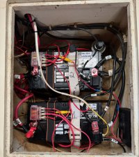
You can see from my photo that there is NOT a direct positive-to-positive connection between the batteries. The positives for both run through the battery switch at the DC panel. There is a negative-to-negative connection for each battery. These are still considered to be "in parallel," correct? I'm having a challenging time finding any mention of this setup and confirming it is considered "in parallel." Every "in parallel" photo I see shows the batteries connected to one another. The 1, 2, Both, Off switch works as expected. I certainly know they're not considered "in series" setup this way. I'm a man that likes confirmation and certainty, so somebody throw me a bone here please.


IMG_0719.jpeg
 
While we're on this subject...(And I apologize profusely if this is Electronics 101 stuff. I'm even reading the 80-pound Nigel Calder book, and I STILL have this question.)

You can see from my photo that there is NOT a direct positive-to-positive connection between the batteries. The positives for both run through the battery switch at the DC panel. There is a negative-to-negative connection for each battery. These are still considered to be "in parallel," correct? I'm having a challenging time finding any mention of this setup and confirming it is considered "in parallel." Every "in parallel" photo I see shows the batteries connected to one another. The 1, 2, Both, Off switch works as expected. I certainly know they're not considered "in series" setup this way. I'm a man that likes confirmation and certainty, so somebody throw me a bone here please.


View attachment 49192
I’m not too experienced with 12v systems but have been poking around the E27 battery system lately and the setup for two batteries is the same: direct negative-to-negative connection between the batteries and the positive wires both lead to the selector switch.

it’s not an indication of anything other than precedence but was somewhat wondering the same thing.

it makes some sense - the selector switch sort of acts like a relay allowing the batteries to operate in parallel or individually. If the two ground/negative posts are permanently connected it should still allow the batteries to operate individually or in parallel.

just taking a stab at this since it’s fresh in my mind but would love to be corrected if wrong
 

Kenneth K

1985 32-3, Puget Sound
Blogs Author
These are still considered to be "in parallel," correct?
Not really enough information here to be able to answer the question:

- Are these the only two batteries on the boat, or do you have another battery/bank somewhere?

- Does the DC panel become powered when only #1 is selected on the battery switch?

- When only #2 is selected?
 
Last edited:

Dave G.

1984 E30+ Ludington, MI
These are still considered to be "in parallel," correct?
Are they connected to the exact same terminal on the switch ? Why are the batteries & cables labeled 1&2 ? Do you have another battery bank on board? If not it appears possible they may only be paralleled when your switch is on both(1&2) maybe ?
 
Top