Maine Sail
Member III
Many boats, specifically sailboats, come equipped or have have used the 5" case Motorola/Prestolite/Leece-Neville style alternator over the years of production. Many Ericson's used the popular M-25's and these engines use this same case style. This case style alternator today is built by Leece-Neville. They are specifically marinized and are called the 8MR series or marine series. They are available many outputs from 37 to 105 amps and in a 2" single foot, 1" single foot, and single ear and triple ear configurations. The regulators though are all the same design.
The regulators that comes stock on most new 8MR series alternators are voltage adjustable but still only single charge stage not three stage.
This will show you how to convert a Motorola/Leece-Neville style alternator to external regulation. Once you have done this conversion you can then use a Balmar, Ample Power or other external three stage regulator.
This particular alternator is a 90 amp Leece-Neville 8MR2070TA with a 1" foot and triple adjusting ears. It fits many Universal and Westerbeke engines as well as some others. I purchased it from ASE Supply for about $200.00 and the conversion kit for $15.00 from a local guy here in Portland.
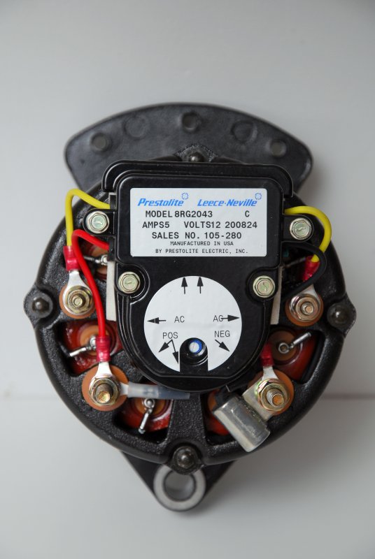
The first step in this conversion is to remove the four machine screws holding the regulator onto the alternator. They've been loosened so it's easy to see which ones they are.
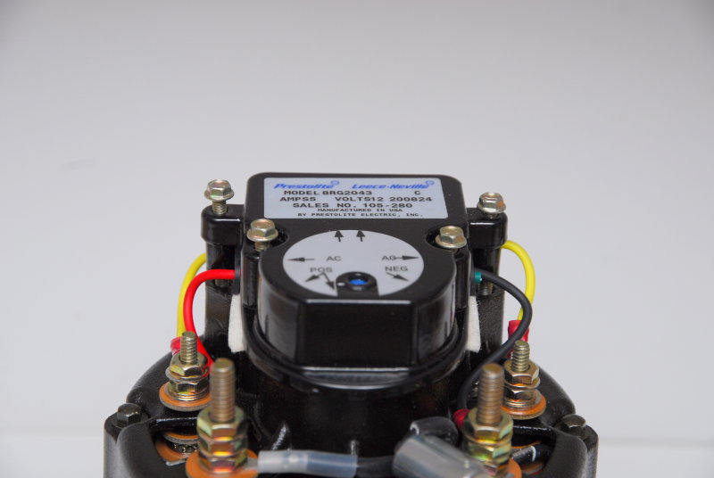
The next step is to remove the four wires that connect the regulator to the alternator. This is as easy and straight forward as it sounds.
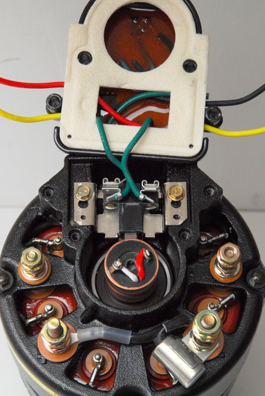
Once the wires are disconnected simply tilt the regulator up to exposed the internal brush connections. You'll need a set of needle nose pliers to pull the connectors off the brushes. This is quite simple and takes about 20-30 seconds to do so.
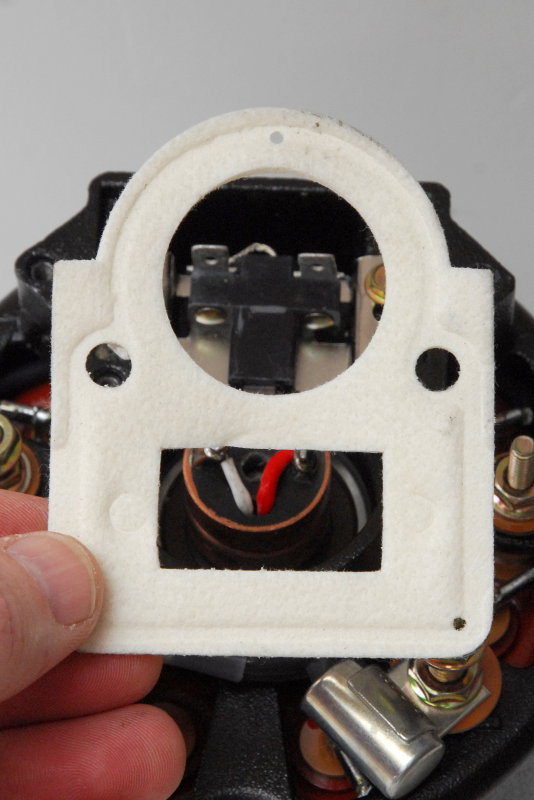
Aside from the epoxy coated finish and general marine construction of the 8MR series this gasket is what makes it USCG compliant and ignition protected. It prevents errant sparks from the brushes from igniting any potential fumes. With most diesels this is not really a huge concern but it's still a good idea to re-use this gasket upon reassembly.
Leece-Neville is nice enough to make an external regulation conversion kit for this series of alternator. The part number is 114-307 and should be available from just about any Leece-Neville dealer.
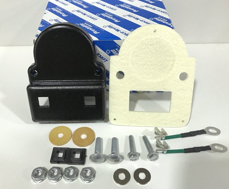
The 114-307 conversion kit comes with everything you'll need, including the wires, bolts and insulators, to make this a simple conversion.
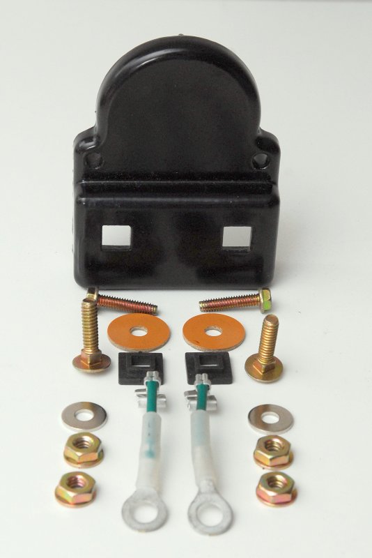
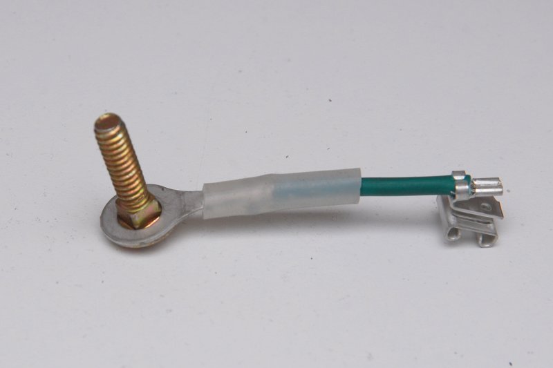
The first step in assembling the kit is to slide the ring end of the wires over the carriage bolts as shown here.
In this step you slide the black plastic insulators over the carriage bolts with the flat side facing the ring and the side with the smaller square facing up as shown.
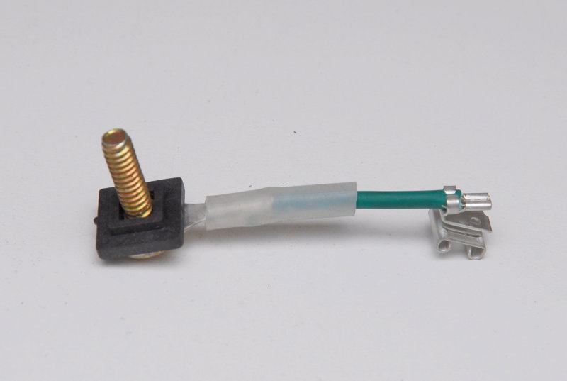
Because voltage is running through these wires they must be installed and insulated correctly so they don't ground out on the aluminum plate. In this picture the small square is properly oriented to prevent the bolt from making contact with the cover plate and will be properly insulated.

With both bolts and internal insulators installed place the large insulating washers over the bolts. Next drop the two small washers supplied on top of the insulators, add the nuts and tighten them down.
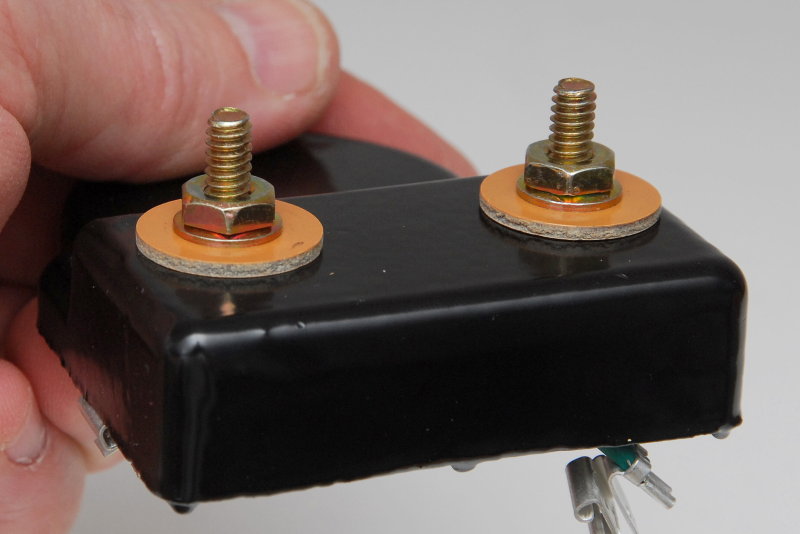
Here's the view from inside the cover plate with everything torqued down and tight.

Slide the contacts onto the brush studs. It does not matter which way you connect these green wires as one will become the field contact and the other will be grounded to the alternators ground stud. Once the wires are connected orient the cover plate over the holes and install teh two retaining screws.

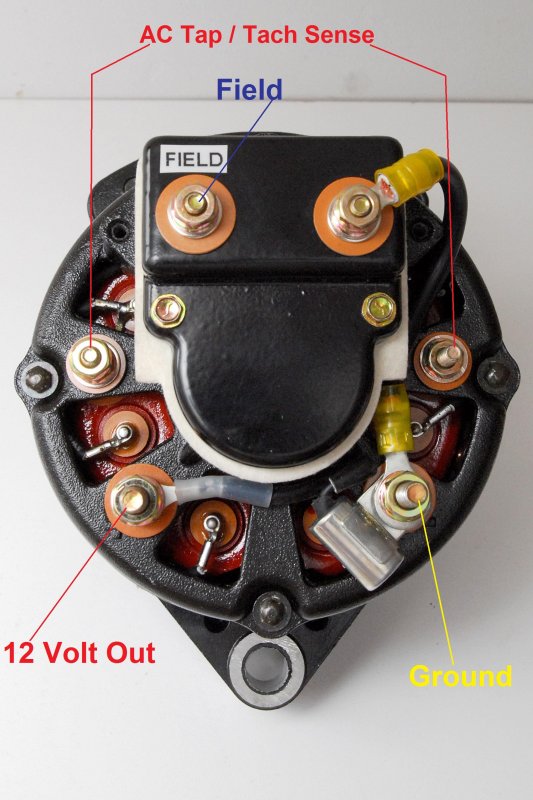
Below is the finished product. One last detail you will need take care of is to create a jumper wire from one terminal of the plate to the ground stud on the alternator. This is the black wire in the photo with the yellow crimp connectors.
Unfortunately my good heat shrink connectors & crimpers were on the boat when I took these photos so I made up a cheap jumper wire for illustrative purposes only.
Leece-Neville recommends a 12ga wire for this jumper. I would also recommend heat shrink crimp connectors & tinned 12ga wire.
If you do not ground one of the cover plate studs, to the alternators ground terminal, the alternator will not work. The alternators ground terminal must also be grounded to the boats ground.
I also labeled the field stud with my label maker so it's easy to wire and remember which is which. The stud marked 12V output gets wired directly to the positive side of your boats electrical system . I recommend wiring this directly to a battery, such as the house bank, so you can't fry the alternator diodes by turning off the battery switch when the motor is running.
For your diesel engines tachometer sense simply wire to either of the studs marked AC Tap. You may need to recalibrate your tachometer after the installation of a new alternator.
Follow the regulators manufacturers instructions for the rest of the install.
This is an inexpensive way to get a brand new, not rebuilt, 90 amp externally regulated marine rated and built alternator for about $215.00
The regulators that comes stock on most new 8MR series alternators are voltage adjustable but still only single charge stage not three stage.
This will show you how to convert a Motorola/Leece-Neville style alternator to external regulation. Once you have done this conversion you can then use a Balmar, Ample Power or other external three stage regulator.
This particular alternator is a 90 amp Leece-Neville 8MR2070TA with a 1" foot and triple adjusting ears. It fits many Universal and Westerbeke engines as well as some others. I purchased it from ASE Supply for about $200.00 and the conversion kit for $15.00 from a local guy here in Portland.
The first step in this conversion is to remove the four machine screws holding the regulator onto the alternator. They've been loosened so it's easy to see which ones they are.
The next step is to remove the four wires that connect the regulator to the alternator. This is as easy and straight forward as it sounds.
Once the wires are disconnected simply tilt the regulator up to exposed the internal brush connections. You'll need a set of needle nose pliers to pull the connectors off the brushes. This is quite simple and takes about 20-30 seconds to do so.
Aside from the epoxy coated finish and general marine construction of the 8MR series this gasket is what makes it USCG compliant and ignition protected. It prevents errant sparks from the brushes from igniting any potential fumes. With most diesels this is not really a huge concern but it's still a good idea to re-use this gasket upon reassembly.
Leece-Neville is nice enough to make an external regulation conversion kit for this series of alternator. The part number is 114-307 and should be available from just about any Leece-Neville dealer.
The 114-307 conversion kit comes with everything you'll need, including the wires, bolts and insulators, to make this a simple conversion.
The first step in assembling the kit is to slide the ring end of the wires over the carriage bolts as shown here.
In this step you slide the black plastic insulators over the carriage bolts with the flat side facing the ring and the side with the smaller square facing up as shown.
Because voltage is running through these wires they must be installed and insulated correctly so they don't ground out on the aluminum plate. In this picture the small square is properly oriented to prevent the bolt from making contact with the cover plate and will be properly insulated.
With both bolts and internal insulators installed place the large insulating washers over the bolts. Next drop the two small washers supplied on top of the insulators, add the nuts and tighten them down.
Here's the view from inside the cover plate with everything torqued down and tight.
Slide the contacts onto the brush studs. It does not matter which way you connect these green wires as one will become the field contact and the other will be grounded to the alternators ground stud. Once the wires are connected orient the cover plate over the holes and install teh two retaining screws.
Below is the finished product. One last detail you will need take care of is to create a jumper wire from one terminal of the plate to the ground stud on the alternator. This is the black wire in the photo with the yellow crimp connectors.
Unfortunately my good heat shrink connectors & crimpers were on the boat when I took these photos so I made up a cheap jumper wire for illustrative purposes only.
Leece-Neville recommends a 12ga wire for this jumper. I would also recommend heat shrink crimp connectors & tinned 12ga wire.
If you do not ground one of the cover plate studs, to the alternators ground terminal, the alternator will not work. The alternators ground terminal must also be grounded to the boats ground.
I also labeled the field stud with my label maker so it's easy to wire and remember which is which. The stud marked 12V output gets wired directly to the positive side of your boats electrical system . I recommend wiring this directly to a battery, such as the house bank, so you can't fry the alternator diodes by turning off the battery switch when the motor is running.
For your diesel engines tachometer sense simply wire to either of the studs marked AC Tap. You may need to recalibrate your tachometer after the installation of a new alternator.
Follow the regulators manufacturers instructions for the rest of the install.
This is an inexpensive way to get a brand new, not rebuilt, 90 amp externally regulated marine rated and built alternator for about $215.00
Last edited: