• Untitled Document

    Join us on April 26th, 7pm EST

    for the CBEC Virtual Meeting

    All EYO members and followers are welcome to join the fun and get to know the guest speaker!

    See the link below for login credentials and join us!

    April Meeting Info

    (dismiss this notice by hitting 'X', upper right)

Oil in coolant?

footrope

Contributing Partner
Blogs Author
Great to see you and Jessie on Saturday, Harold.

I got the 4 injectors out. The 4th had to wait overnight for a penetrating oil treatment and a cheater for my 1/2" ratchet.

Compression check: I'll check with the engine shops for adapters for the compression checker, but I'm not holding out hope I can borrow one
 

footrope

Contributing Partner
Blogs Author
Update

Compression test: Looks OK, I guess. I found a Pittsburgh diesel compression checker for $30 at Harbor Freight. I used the glow plug adapter. Problem is, unless you can get the injector tubes off the injector pump, you can't get to the forward glow plug. My fuel tube nuts are stuck on the injector output nuts and I didn't feel like dealing with the springs and innards of the injector pump outlets in that environment (paint chips). So I did that forward cylinder with the M24 x 2 injector adapter and it acted about the same, but the fitting isn't a great way to do it with the tester kit components. The injector adapter either bottoms out on the head or, of you use the spacer, it won't engage enough threads. The adapter is softer than the head and will strip. I made a video of the runs, since the gauge or the hose or fittings aren't holding pressure well. After about 8-10 compression hits, the gauge reaches 300 on each cylinder. Keep in mind this is a cold engine and I can't run it. I wasted too much time struggling with the injector tubes where there is no room to work. Oh, and the engine wouldn't turn over initially. I think it was a loose or dirty solenoid connection. I used the house batteries to do the tests.

Head removal: The rocker arm shaft and rockers came off easily. Need a 12mm deep socket. The valve lifters show some wear on the bottom end, as expected. Still need to look at them carefully. They are not hydraulic, they're solid. I was able to get the head bolts loose with relative ease (!) using a 3/8 drive ratchet with a 4" cheater. The ones at the rear that were not under the valve cover (and not bathed in oil) were the toughest. One had the washer broken and was quite rusty and hard to turn. I had to use the 1/2" drive with a short cheater to break that one loose. Penetrating oil would have helped but I didn't stop to spray any. The bolts under the valve cover were easiest. At the rear corner of the head on the intake side is a coolant port, so that is a plug with a gasket, rather than a head bolt.

Prepping to lift the head involved some miscellaneous work.
1. I should have flushed the rest of the coolant out of the head, but didn't think of it until the head was broken free and it drained out. I'll probably have to vacuum out the oil pan.
2. Removed the exhaust flange from the exhaust manifold. Using penetrating oil (Bolt Blaster) made the job easier on the three nuts. I enclosed a picture of the carbon build up from the 10 seasons we've used the boat. My custom SS elbow collected some souvenirs of those years. Can't wait to see how much carbon I can't see. I need to clean that out every couple years. I have noticed a drop in power.
3. Remove the negative cable (ground) from the exhaust manifold.
4. Remove coolant hose from rear of exhaust manifold. Also remove coolant hoses and thermostat from front of engine.

The head broke free easily with a little effort with a small nail lifter bar. One of those crooked ones that carpenters use. The head and manifolds are heavy and I'll have to prop it up with some shims or starboard as I raise it. It has to lift about 4 inches straight up before I can muscle it out of there over the two studs.

I had to use the shop vac quite a few times to collect the paint chips. There are three colors of paint. Red, which seems to be the original or primer color, blue and Universal gold.

The 8th and 12th bolts from the left show a lot of soot. They are from near the injector ports.
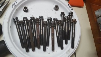
20160601_Head_Bolts02-small.jpg

The carbon build up of 10 cruising seasons inside of the SS exhaust elbow, near the water injection fitting.
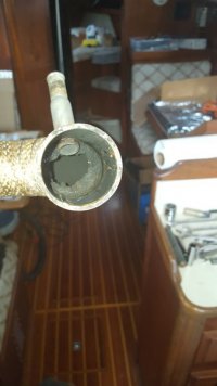
20160601_Elbow_Carbon02-small.jpg
 
Last edited:

footrope

Contributing Partner
Blogs Author
Head is ok

Got a call from the machine shop. Head cleaned up and pressure tested good. No cracks or leaky valves. It was a little out of shape so they machined it flat.

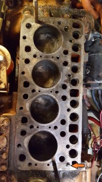
The tops of the pistons look good. No visible cracks in the block. Is there a good way to check the mating surface of the block for flatness? I will clean it and emery paper a little staining, if needed.

There was no shim between the head and block, just a gasket. Is the shim optional?

Now that I know the head is good it's time to order parts and clean up the exhaust and intake manifolds.
 

footrope

Contributing Partner
Blogs Author
A little more info on the valve train.

Six of 8 tappets look very good. The other two need to be pulled and checked. I am assuming that if the tappet surfaces that ride on the cam are good, then the cam lobes are ok, too? There are absolutely no visible marks on the tappets. I haven't rotated the engine by hand yet to try to look at the cam.

All of the pushrods have a small mark on the bottom end. A few have wear marks moving up the ball a little. I wonder if they should be polished?
 

hodo

Member III
Oil in Coolant

Hi Craig. To check the block surface for flat, you will need a straight edge, and feeler guage. Not sure what the specs are, but I would guess anything under .002 would be good. If no scarring on lifters, cam should be fine. Depending on the amount of wear and the pattern, I might end for end them. When you clean the surface of the block, place an oil dampened rag in each cyl , to catch debris. I don't recall ever seeing a shim with the head gasket. When you reinstall the head, be aware that there is a toque sequence you need to follow. You can call me on my cell if you have questions. Also, clean the head bolt threads with wire wheel and check them for stretch, or any narrowing. The washer under the bolt head is a hardened washer. If it was broken, that may have allowed coolant to travel through the gasket. Good Luck
We are headed to Kingston this weekend.

Harold
 

footrope

Contributing Partner
Blogs Author
Thanks, Harold. Have a great time in Kingston.

Mr Kubota also said that if there wasn't a shim, then one isn't needed. Yay, saves $50. I am getting a quote for the gaskets and new head bolts and washers today. Got the cooling jacket/exhaust manifold, intake manifold, exhaust elbow and the end plate with the lower t-stat housing in to get them cleaned up, de-greased.

When you say end-for-end the lifters, you mean invert them? They are not identical on both ends. The top end is a cup. I did keep them in order so each one could go back in the same spot.

I will try to get a shop manual to help with the head installation procedure. No doubt I'll be calling you. I have a torque wrench on loan from a friend.

How should I clean the threads in the head bolt holes? Several are rusty. I'm not sure how I would clear those out effectively. I have been told that the bolts should turn easily (clean threads, lightly lubed) to endure the torque is transferred to squeezing force and not turning force.

Oh, and the injectors are in for testing and repair. One was about 200 psi higher to crack than the rest and may need a new part. The injector folks recommend Stanadyne fuel treatment - any comment on that?

Cheers!
 
Last edited:

hodo

Member III
Oil in Coolant

Craig, sorry I wasn't clear. I was talking about end for end on the push rods, if they have a ball end on each end. Best way to clean the internal threads is with a thread chaser tap. It needs to be the "bottoming" type, so it will clean further down the threads. Make sure it has the exact pitch as the original threads. Use tapping fluid or some light lube on the tap for each hole. If the holes are not blind, and go into the coolant jacket, using grease on the tap will collect the debris, if they are blind, you will need to blow each one out, with air. Make sure the debris doesn't fly into any openings. And, Stanadyne is good stuff. Follow the directions on the bottle ,don't over treat. Should be a good weekend to do the repairs. It's supposed to be cool and chance of showers.:egrin:
Harold
 

footrope

Contributing Partner
Blogs Author
Thread chaser tap. I'll look for one. Getting the torque right is pretty important. Maybe McLendon's or Stone Way Hardware. But I'll check at the big box stores too. At least some of the head bolt holes have a bottom.

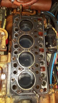
I was told how the head gets oil. There is a fitting that looks like a grease zerk at the forward corner of the block, on the exhaust side, that feeds oil into the head. It has its own extra, round gasket. All the other holes on the top of the block are coolant, tappet, oil return or head bolt holes. When I picked up the head I asked how the magnaflux crack test works and whether they can detect cracks anywhere in the head. I was told that the test is reliable for the whole casting. Picture of the block is attached.

The gasket parts that have to be ordered aren't promised to me yet. Hopefully today they'll quote me with a delivery date. The injectors won't be ready until early next week. When I dropped them off the mechanic immediately had me come back and observe the crack test, but they had a bunch of work waiting there on the bench. They also work on injector pumps, so I filed that away for the future. He said the injectors should last for 5,000 to 10,000 hours with clean fuel. Hence the Stanadyne suggestion. The out-of-spec injector was sometimes leaking a straight stream of fuel.

I probably won't get to the installation for awhile. The family starts arriving Saturday and my Mom will be here for two weeks. We have a lot planned, but no boat rides because of this situation. In fact I think I'll put a light coating of oil on the top of the block and on the cylinders. Also should suck the rest of the coolant out of the block. There is already a little light rust in several spots where the head gasket was failing. I have some 1000 grit emery paper for that. But right now I have some small pieces of furniture to build.

Cheers!

20160602_145257-small-arrow.jpg
 

footrope

Contributing Partner
Blogs Author
Back on the project

The fun of marrying off my daughter is complete and the last family member has returned home.

I received the parts I ordered from the Kubota dealer last week. They didn't seem to be able to order the gasket for the valve cover, so I'll re-use the old one or check with a marine dealer.

The new head bolts have a washer built into the head. I guess I won't have to re-use the old flat washers (?). There didn't seem to be new washers available.

Thanks to a nearby thread I found this link to downloadable Universal Diesel Manuals, including the Service Manual I needed that describes torque and the head bolt tightening sequence. Interesting read so far:
http://shop.toadmarinesupply.com/ma...tion&finalcrumb=Universal+Publication+Listing

1. The head shim requirement is determined by measurement of top clearance. Not sure exactly how to do that or if it is absolutely necessary. There is a short explanation in the manual. More info: The top clearance can be checked with a piece of solder, that isn't too much thicker than the actual clearance, after the head is torqued down. So, a test fit of the head should be done and each cylinder checked by rotating the engine.
2. Head bolt tightening is from the inner sets and progressing fore and aft, finishing in the front of the engine.
3. Torque values are low, as stated in an earlier reply. 54.2 to 57.9 ft-lb.
4. If the engine has not been run for a long period then the cylinder head cap screws should be re-torqued. Valve lash should be checked after head screws have been re-torqued. Very interesting.

Cheers
 
Last edited:

footrope

Contributing Partner
Blogs Author
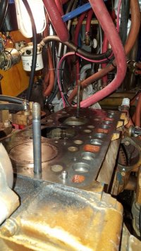
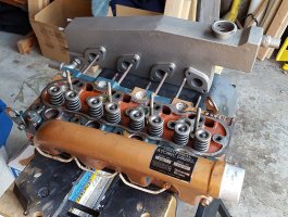
I have done two test-fits of the head without the manifolds installed. On the second test, yesterday, I fully torqued it down using the new gasket and measured the top clearance using some 0.062" dia wire solder, which crushes nicely. Inserted through the glow plug holes. All is well, there. The top of the piston and the bottom of the head have adequate space, about an average of 0.040” across the 4 cylinders. I used a pipe wrench to turn the engine. The pistons come right to the top of the cylinders, which is desired.

Prior to this step, I used a straight edge and a 0.002" feeler gauge to check the top of the block. No low or high areas at all. I couldn't find a M10x1.25 thread chaser tap, so I made one out of a clean old head bolt. I cut 4 grooves across the threads and it worked ok. Clearing out two especially contaminated holes. Note: Using a regular tap for this job is not a good idea, as it will cut the existing threads thinner.

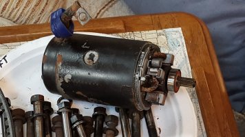
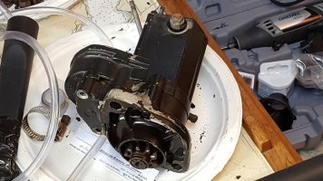
I took off the starter. It is a geared unit. The electric motor separated easily from the gear unit, and the shaft is surprisingly small. Bearings and brushes are good. I just cleaned it up a little and put a tiny bit of new grease on the spline of the electric motor before putting it back together. The teeth on the output gear are good. It awaits re-installation and I am pondering a hasty re-paint, but probably won’t do that. The flywheel has shiny gashes on a few of the teeth, but nothing alarming.

The injector pump ports are available directly since the intake manifold is out of the way. I wanted to take the output ports off to clean them but chickened out. The output ports are now very tight since I can get to them using a deep socket. The tubes that carry the fuel to the injectors all were slightly bent when I was removing the head, because I couldn’t break them loose from the ports due to the restrictions with the head in place. So, I’ll re-align them gently when I get to that point. They’re steel, so no problem with some minor bending. I have them off for cleaning up. So much chipping paint.

I have the head at home now to finish cleaning it up and will install the intake manifold and glow plugs here. The exhaust manifold is so heavy, I’ll install it inside the boat just prior to putting the head back on. I did check the fit without the new exhaust gaskets. Looks good.

There are a hundred steps to get to the point of starting the engine, but at least I am in re-assembly mode now. With the low head bolt torque, I am conscious of the need for clean threads in the block (already cleaned) and clean holes in the head. After the test fit yesterday, I still need to clean a couple holes in the head that apparently have enough rust in them to drag on the bolts. The 57 ft-lbs torque requirement is so light that even a little drag is not desirable.

I am contemplating adding an oil pressure gauge. At least I want to check oil pressure. Access is a problem, though. The oil pressure switch is right above the starter on the left side, and just below the block surface. Everything is in the way of that area.

20160708_185014-small.jpg20160706_175724-small.jpg20160706_175743-small.jpg
 

footrope

Contributing Partner
Blogs Author
Ceramic coating on exhaust manifold/cooling jacket?

I dropped off the exhaust manifold at a coating company today. Initially, I was going to get it sandblasted and then paint it myself with VHT engine paint. Well, I talked to the guy a little about the coatings they do and decided that it might be ok to ceramic coat the manifold/jacket.

Pro coating
- Less heat radiated to the engine compartment
- Coating is less likely to peel or chip than paint because it is designed for up to 2000 degrees (F or C? Doesn't matter)
- Titanium color (think of a matte bronze) is nicer than the Universal gold/copper paint that is peeling off the rest of the block and head

Potential cons
- I don't know how much additional heat, that presumably will be kept in the coolant, will affect the delicate balance of the cooling system. I'm not too worried about the muffler though.

I'm interested in any comments or experience with ceramic exhaust system coatings, whether in marine or automotive usage. The coatings guy claimed that they ceramic coated the exhaust/cooling jackets for the guys with the big motor yachts. Oh, and he said that the ceramic can be sandblasted away if necessary. He said they used garnet blasting media.

Thanks!
 

Guy Stevens

Moderator
Moderator
I am thinking of having the exhaust riser done for my gen set

Putting my Gen set and 60gph water maker together, and am thinking of having the exhaust riser done in Ceramic coating. I wonder how it compares to a fiberglass wrap.

If I might ask how much did you spend on the coating?

Thanks,
Guy
:)
 

footrope

Contributing Partner
Blogs Author
Putting my Gen set and 60gph water maker together, and am thinking of having the exhaust riser done in Ceramic coating. I wonder how it compares to a fiberglass wrap.

If I might ask how much did you spend on the coating?

Thanks,
Guy
:)

Guy,

I paid $140 before tax. They use a flow through cleaning process, so the garnet blasting gets the inside pretty good. The blasting was done twice, using a finer grit the second time. Then they spray the ceramic on and bake it. The inside is also coated, at least the areas I can see. I got a $25 quote for just the sandblasting, but I don't know if that was the two-stage blasting or just one pass. I'm looking forward to the results after I get it running, which might be this weekend. They turned it around in just two days, too.

Craig
 

footrope

Contributing Partner
Blogs Author
Cleaned up the top of the block. Final cleaning and oiling of the tappets. Final check of the valve push rods. Found two or three with small nicks on the lower end. Used 1000 grit to polish that out. Will check again after running the engine when I re-torque the head.

Head installed and torqued. Used a Q-tip to get grunge out of the bottom of the bolt holes. I had to chase three of the bolt threads again during the torquing process, but that went ok. Exhaust jacket installed after some sidewall disassembly. It was much easier to drop the head over the studs by itself and then shoehorn the exhaust jacket on its 8 studs after torque was applied.

Restored the rocker arm assembly and adjusted the valve lash. A bit tricky, but after four passes I figured out that I needed to go a little further past the beginning of the compression stroke before measuring the clearance. Installed the valve cover and installed temporary breather line. Still looking for a line size that will fit on both ends.

Ran the electric prime pump before installing the injector lines. The injector pump ports leaked a little around the nuts. I have them tight and I wonder if the packing actually works better if I back off slightly? We'll see when we turn the engine with the starter to flush the ports and lines. I got clean fuel out of the bleed line.

Pumped out transmission and refilled to proper level with ATF.

Cooling system flush: Used a small shop vac to pull fresh water through the engine. Poured water in the thermostat housing and ran the vac until clear water ran through the little hose I was using. I did a similar flush of the coolant that was left in the water heater. So, now all the parts of the cooling system are cleaned or at least rinsed of the oily coolant.

I thought of making a flush fixture that could take a water hose directly, with a valve to regulate the flow and shut it off, but in the end just used the vac. I don't have an air compressor to chase most of the remaining water out. Also, there is no "draining" of the coolant because the engine sits an an angle, making the low point at the aft end of the engine. As long as I can get a gallon of coolant into the system it'll be ok.

Heat exchanger installed and all lines connected. Almost done with the contortionist part of this re-assembly. Cleaned the thermostat of residual oil. Just about ready to fill the system.

Exhaust flange and elbow installed and new raw water exit line hooked up to the elbow. All lines secured above water line as before. There is a "T" fitting in the raw water exit line and the stem of the tee is hooked to a 1/2' dia. line that runs all the way aft to the 2" street elbow on the exhaust thru-hull. Must be a siphon break? I always wondered what that line on the elbow was connected to.

It has taken a long time to get to this point, especially with nearly a month off for the family event, but much of the work has involved unfamiliar tasks. Hopefully just one more post to describe how well the engine ran and then we can resume cruising.

Cheers!
 

footrope

Contributing Partner
Blogs Author
Wishful thinking

Well, I'm hoping that the leaking injector pump output ports were either allowing air into the injector lines or simply reducing the pressure to the injectors enough to sabotage the spray pattern or fuel atomization or something. The engine primes, but won't start. I managed to hydraulic lock it with fuel and cleared it by taking the injectors out.

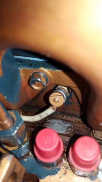
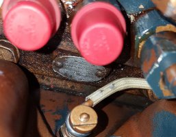
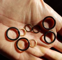
After consulting with the injector shop, I removed one output port and it has a brittle rubber o-ring. Not surprising it's brittle. I found a part number for the leaky o-rings on my favorite Kubota website and the injector shop is looking for a replacement also. The injector shop called this morning (7/28) and said they had the parts ready. There is also a thin copper washer under the nut that I didn't see. So I have replacements for those, too. I didn't even notice them. The injector shop is closer and they had them on the shelf, once they knew what I needed. I also found out that the injector pump is a Nippon Denso 094500-0622 by cleaning and reading the little oval tag.

Every move on this engine is a new reason for 3 coats of paint to chip off. Copper, red, blue. So twice as much time is spent carefully dealing with paint chips as it takes to actually turn the wrenches.

Tag location
20160727_143447-small.jpg

Cropped and inverted. Tag says 094500-0622, ND-PFR4M55 / 1ND062 8S Kubota V1500
20160727_143447-small-crop.jpg
 
Last edited:

footrope

Contributing Partner
Blogs Author
Running smoothly

Ok, this 5432 engine (maybe most of the 5432/M40 engines) was tough to bleed after taking off the fuel lines between the injector pump and the injectors. It takes a lot of cranking to drive the air out of those lines, I think. I'm sure I heard it somewhere that getting the air out of injected fuel systems is important?

After replacing the o-rings and thin copper washers on each of the injector pump ports, it took a lot of cranking and bleeding (of fuel) to get the engine running. What I finally tried was to crack the injector lines loose at the injector end and crank the engine. I got cylinders 2, 3 and 4 to seep fuel at the nut after that. I tightened the nuts back up and then good things started to happen. After some more cranking and sputtering the engine finally kept running.

Fixing the leaky injector pump ports: The o-ring on the injector port resists as you unscrew them. The spring under the port will probably not jump out, but be very careful not to knock it into the bilge when you lift out the port. The other parts underneath the spring should be left in and kept clean while you clean the port and put on the new gaskets. The injector experts recommended vaseline to lube the o-ring when screwing the port back in. I used some light machine oil. Proper torque should be observed - 28-32 ft-lbs according to Denso.

The engine ran cool enough. 140-145 deg F with light loading - forward gear and 1100 rpm - if I believe the gauge. The ceramic coated cooling jacket got plenty hot to the touch. I doubt it will make any difference that I'll be able to detect as far as passing more heat on to the exhaust or heat exchanger. I just hope the coating lasts a few years.

Tomorrow I'll go back to top off fluids and run it some more. There is still residual oil in the cooling passageways that is coming out. After a few hours I'll change the oil and coolant again before heading off on a cruise.

Side note: Denso does not have any online support for these old injector pumps at this time and there is very little elsewhere as far as reference material for them. My injector experts still can get parts and some support, but the online info from Denso has been taken down.

The old gaskets for the injector pump ports:
20160731_180628-small-crop.jpg
 

footrope

Contributing Partner
Blogs Author
Too happy too soon

Yes, there finally is fresh oil in the coolant. It took about an hour and a half of running to show up in quantity. So, either the block is bad (cracked) or there is a way for a head to be cracked and not show on the magnaflux/eddy current or whatever crack tests the head shop performed. Or, I totally messed up the head installation. I recently ran across this Kubota site (oragnetractortalks) that detailed how the freeze plug that is behind the gear case can leak, causing oil to fill the radiator.

I really don't know what to do next, but the orangetractortalks dissertation on oil in the coolant is pretty good. The engine in the example is an old one and the gear case is similar to mine. I've already checked the frost plugs under the valve cover, so the pressure tests are next, I think. I didn't find this site until the head was checked out and re-installed, naturally.
 
Last edited:

footrope

Contributing Partner
Blogs Author
Head lifted

A friend and diesel mechanic (one of my consultants) came to the boat the other day and brought a cooling system checker with a gauge. We verified a gradual but steady leak and that coolant was transferred to the crankcase during the test. Not great news. My gamble on the gasket being the problem lost.

The second time lifting the head went smoother and with less disassembly this time. No need to remove the heat exchanger. I did it in about 4 hours with a pause for lunch. I used a hand pump to get the coolant level below the deck surface. Small pump but impressive performance ($5.99 at Harbor Freight, but added my own suction tubing because the included tubing collapses).

Despite talking to several yards and companies about labor costs and scheduling to replace the engine, I was persuaded to check the job I did on the head gasket. It seems to be fine. Good head gasket contact and the little o-ring for the oil pipe was not cut or compromised.

So, now to figure out if the block is bad, or if a problem with the head was missed. From the description of the leak testing procedure at the head shop, I have to think it is in the block. The oil pipe is secure, still no visible cracks around anywhere on the deck surface. So, now we're brainstorming how to test the oil pipe or the passage in the block. I can see some "casting slag," for want of a better term, in the adjacent oil return passage. I can also feel a very rough area below the oil pipe, by putting a finger down the round cooling port on the other side of the pipe.

I have a PYI dripless shaft seal, rather than a stuffing box, so I've been advised to haul the boat for engine removal. I was also told by one engine guy that the "oil" was probably the lining of a deteriorated coolant hose and that I should flush the cooling system and run the engine again. He was right that I have old coolant hoses, but mine are in good shape. In fact he installed them 12 years ago. I am not recommending to let your hoses go for 12 years.

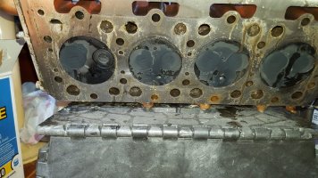
Head gasket on block
20160805_160001-small.jpg
Bottom surface of head
20160805_160609-small.jpg
 

Guy Stevens

Moderator
Moderator
The question is one of which half is the issue

If the block is cracked then you are going to need a new block. You seem to have checked most of the other particulars (casting plugs, and the like). What remains if the head is not the leak?

Can you get a new or refurbished tractor block for it? Seems like a short block (except that you would have an extra head then), could be an easier route than trying again with the chance of again assembling without fixing all the issues with the existing block.

(This was a support post for you, not second guessing you, just providing some thoughts, like if we were at the bar, drinking Mai Tais....)


Guy
:)
 
Top