Waterline and heeliing.
Joe, Some explanation is necessary.
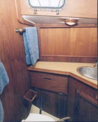
1. Hull #55, Head #1.jpg is simply for orientation. It shows the raw water intake in the bottom right corner of the photo coming from a seacock under the head sink. It will be useful to know that in the next photo. By the way, that's the starboard side of the boat you're looking at with the head facing aft against the bulkhead that separates it form the V-berth.
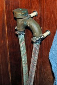
2. Hull #55, Groco vent 3/4".jpg shows the raw water intake hose on the right attached to the Groco vented loop where it reads IN. The other side of the loop leads to the intake of my Groco K-H head and reads OUT. Those white spacers come with the bronze loop.
By pumping the head you can see that I'm pulling water past the loop, opposite to the way the vent was designed to operate. To make the vent close, one would have to push water through the loop and that was not what my intent ever was. By sealing that hole, the water can be drawn up and past the vent to supply the toilet. It requires me to use a finger to seal the hole at the same time I pump the head with the other hand. Of course, this would work with an electrical head as well. It's simply the safest failsafe method I could come up with. Like I said earlier, that vent is at about chest height, as close to the center line of the boat as I could get it. It might interest you to know that in a conversation with a tech rep at Groco years ago, I mentioned my use of that vent in reverse and he responded by telling me that he recommends that same method.
I think the layout of your E25 is possibly the same as my E31 in that the head is on the starboard side just aft of the V-berth. That being the case, the loop is mounted on the bulkhead separating the two and to the left, in the corner of the head enclosure.
The loop is through bolted with really cool barrel nuts on the V-berth side of the bulkhead (see page 566 in the 2007 West Marine Catalog) and Phillips head machine screws in the head that you can see. I added the flat washers at the bulkhead to help spread the load when/if grabbing the loop in heavy seas, etc.
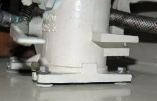
3. Hull #55, Groco standoffs.jpg shows stacked 1/4" Nylon flat washers (page 581 in the 2007 West Marine Catalog) I installed between the bronze toilet base and the fiberglass riser it's lag screwed to. There's now an air space between them which allows me to pour a glass of fresh water in there to wash salt, dust and hair away so it can't remain, turn green and stay damp. I stacked two or three washers and bedding compound under each lag screw as best I can remember.
Note also the raw water feed hose on the right of the photo leading up the bulkhead to the loop and the supply hose from the other side of the loop on the left, clamped to the head raw water intake barb.
I hope I haven't confused you and that the photos will be of some help.
Later,
Glyn
")