Solar Set-up - Continued
I found the answer to my previous question -- yes, normally a small groove is drilled into the stainless steel rail so the pointy set screw holds more firm and can be screwed in flush. Not a hole all the way through, but just an indent.
That being said, I have made progress on the solar set-up which put me on the path of discovery of the next level of problems as well as a rejection of my mini davit assembly due to aesthetics.
After 5 hours to get the wiring <ugh> ... I am mounting the panels on the aft rail and I completely envisioned going under the cockpit, following the other wires that extend from the starter panel though the engine compartment then follow the low gauge wires to the batteries, I found <what i="" though=""> was a much more simple (and shorter) run. I ran the primary wire down the aft/top of the quarter berth and followed the power lines that go to the stern light. This was easy and much shorter ... I mounter the solar controller and panel under the chart table far to port so your knee won't hit it and it is out of the way (visually and ascetically). I eventually wired it back into the battery switch but in that location I can easily extend to the battery compartment if I want to change it... there was a nice space on my E-35 there and a small compartment that opened behind the drawers and under the map cylinders below the chart table.
Then, I encountered the next set of problems and a few questions (in
RED):
1) With the solar controller on and no load (no panel connected), it was incompatible with my short power charger. I took all sorts of interesting notes (like differences in the solar control indicated battery voltage and the DC panel digital monitor) with short power attached and AC charger engaged. What would happen is when the short power charger would switch from absorption mode to float mode it would drop to the defined 13.5V for about 10 seconds and then switch back to absorption mode ... and them, per the manual, it would stay there for 1 hour and try to go back to float ... same thing, repeatable. I found a nice article here (external link:
http://roadslesstraveled.us/charging-rv-marine-batteries-solar-power-shore-power/ ) which gave me some good ideas on the cause but decided I would just avoid the issues with a manual switch to disconnect the regulator from the loop and mounted the switch on the DC panel on the lower-right unused portion. I was also concerned about the interaction with the alternator/regulator but the switch would avoid potential issues there, also. FYSA, controller is Morning Start SunSaverDuo.
Does anyone see any issues with the switch? I placed it inline with the high going out of the the solar controller to the battery positive on the battery switch ... makes sense to me since it avoids controller dueling problems and I don't need solar charging anything when I have shore power or while under power.
2) Was intended to permanently mount one panel on a "mini-davit" that looked great on paper but not in person ... so rejected and determined both would live as more removable panels and I would connect them via a flush deck plugs on the transom. My daughter, who has impeccable taste for design of all things gave the mini-davit a huge, immediate wince upon first sight <eek>. I did get to hook the panels up to test full functionality and two 30 W panel drove 3.7 Amps in the morning sun and look more aesthetic clamped to the push-pit top rail.
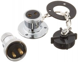
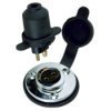
Last question, deck plugs ... my intent is to get flush mounted plugs (one for each panel) and mount them on the aft transom. I have observed these plugs on other boats and my daughter has already given a positive endorsement. I am struggling with deck switches and wanted to see if there was anything I am missing... i can only find a few manufacturers of these Perko, Hella, SeaDog (I am looking for something like the attached images). It is a little frustrating that most of them seem to only handle high gauge wire or don't publish which gauge they are compatible with... for some, I can even find photos of other aspects except the stock advertising image to see what the connections look like or how large of a hole the flush mounted ones require. I have found some comments on the usual commercial websites but not always consistent -- I am quite disappointed in the manufactures' documentation for these products that would support a blind, online buy without seeing the item in person. Based on my equations for length/voltage drop, I used 10 gauge wire back to the transom and was willing to go down to 14 gauge to accommodate the plug and solar panel junction panel for short runs with both panels dumping into the single line to the controller.
Am I missing any good plug options? Different style than those shown below? Any advise using these types of deck plugs?
Thanks for everyone's help thus far -- though this thread started as "sizing a trickle charger" I have learned a lot since this project made me examine/think deeply about many aspects of the boat that I haven't to this point (including mapping out about 50% of the mess behind the DC panel).

</eek></what></ugh>