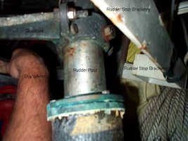
There are really no stops
The force of the rudder hitting the two longitudinal bulkheads will continue to allow this to happen.
The solution is to tie the two bulkheads together. Simplest way to do this is a weldment that goes aft of the rudder post, and is thru bolted to the bulkheads.
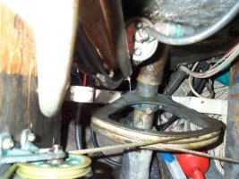
The rudder needs to be fixed, and the stops correctly fabricated. Here is one of the best ideas that I have seen so far.
Another idea would be to come down from the cockpit bottom with a weldment that contains a pipe, although on the 39 this pipe would be too long with to much force applied to the bottom of the pipe, with mechanical advantage it would tear the pipe out of the fitting way too easily.
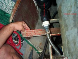
The bulkheads will have to be refastened. On Pneuma I glassed a longitudinal piece of wood to the hull that was 2 layers of 3/4 inch plywood. It was glassed in really well, then the two bulkheads were thru bolted to this, same on the top, which I glassed another layer of 3/4 inch plywood just in from the edge of the cockpit turn. The top of the bulkheads were attached to that via thru bolts again.
The distance apart on Pneuma allowed us to make the weldment the stop instead of the bulkheads. If you look there are two little squares welded into the inside of the U in the photos, these were the actual stops. They had the advantage of being subject to less mechanical advantage, and of making the load one that was fore and aft instead of wedging the bulkheads apart. (The weldment was done by a former owner, I did the work on the bulkheads to make them more secure, as they had come adrift from their tabbing at the bottom.
The reasoning behind using the thru bolt installation on glassed in longitudinal knees, was that it allowed me to remove the bulkheads to access the area which was the old fuel tank, and more importantly the area where the shaft strut mounts.
While fixing the rudder go ahead and make it bigger per Bruce's plans for it.
This should give someone some ideas. It sounds like a huge project, but it isn't as bad as it sounds. The glassing goes quick, and the weldment is generally fabricated by your local metal man. I would make it out of aluminum if I were doing it from scratch, not the mild steel that way used on this one.
Guy
")
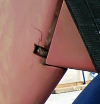 Rudder hairline.jpg137.2 KB · Views: 127