davisr
Member III
I've spent a lot of time reading Don Casey, Nigel Calder, and the many helpful postings by MaineSail on this and other forums regarding rewiring projects. I have several charts and diagrams that I'd like to pass by everyone soon in order to get some learned opinions. First, though, I would appreciate everyone's help with one matter that remains a stumbling block for me - the grounding of my AC and DC systems.
Like many owners of boats in the 27 foot range and under, my Ericson 25 has not an engine, but an outboard, specifically a Yamaha 9.9 high thrust with an electric starter. Neither Casey nor Calder address the issue of outboards, although Calder does state the following, "although it is common practice to select a substantial bolt on the engine block as the DC main negative bus, this is not the best choice. It is preferable to set up a separate bus bar," Boatowner's Mechanical and Electrical Manual, p.232.
Calder goes on to say that this separate current-carrying bus bar, which he calls the DC Negative Main Bus, should, in turn, be connected to another noncurrent-carrying bus, which he calls the Grounding Bus. He notes that this Grounding Bus is also known by the following names: Common Ground Point, Central Bonding Strap, Equalization Bus, and DC Grounding Bus. Calder then says that this Grounding Bus should itself be connected to an immersed Ground Plate or Ground Strip. Calder has a good diagram which helps to simplify things, but to simply things with words I'll summarize as follows:
DC Negative Main Bus ----- Grounding Bus ----- Ground Plate
Calder's suggestions will likely cause many to bristle, since the issue of ground plates/ground strips and lightning protection is a hotly debated one, but I bring all this up only for the sake of the issue at hand -- finding a ground for my AC and DC systems. Back in May of this year, there was an active thread on this forum with the title "A/C Grounding Question." On that thread, Maine Sail posted the ABYC regulations on this subject. I have placed in bold the section that I believe pertains to my boat.
Maine Sail said:<O ></O>
></O>
If you want to wire to current suggested and accepted marine standards:
ABYC E-11
11.5.5.3: The main AC system grounding bus shall be connected to
11.5.5.3.1 the engine negative terminal or the DC main negative bus on grounded DC systems, or
11.5.5.3.2 the boat’s DC grounding bus in installations using ungrounded DC electrical systems.
11.5.5.4: In AC circuits, all current carrying conductors and the grounding conductor shall be run together in the same
cable, bundle or raceway.
11.5.5.5: There shall be no switch or overcurrent protection device in the AC grounding (green) conductor.
11.5.5.5.1 Where isolation of galvanic currents is desirable, only devices meeting the requirements of ABYC A-28, Galvanic Isolators, shall be used in the grounding path
I believe that since my Ericson 25 has an outboard motor instead of an engine my DC electrical system would be considered ungrounded (but I'm unsure). At any rate, the ABYC, in this section, uses the term DC grounding bus. This is one of the terms that Nigel Calder says is used to refer to the bus located near the Ground Plate or Ground Strip.
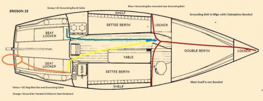
The Ericson 25, apparently unlike larger Ericsons, was built with a Ground Plate or Strip of some sort. On my E25 (and I know on at least one other), there is a bolt in the bilge near the mast compression post. To this bolt are connected wires from the chainplates (starboard, port, and forward). Based on everything that I've said above, it seems that I should use this bolt, or at least a bus that I install near it, as my Grounding Bus or Central Grounding Point for my AC and DC systems. I've attached a diagram that will hopefully make things a little more clear.
I welcome any suggestions.
Best regards,
Roscoe
E25, #226
Like many owners of boats in the 27 foot range and under, my Ericson 25 has not an engine, but an outboard, specifically a Yamaha 9.9 high thrust with an electric starter. Neither Casey nor Calder address the issue of outboards, although Calder does state the following, "although it is common practice to select a substantial bolt on the engine block as the DC main negative bus, this is not the best choice. It is preferable to set up a separate bus bar," Boatowner's Mechanical and Electrical Manual, p.232.
Calder goes on to say that this separate current-carrying bus bar, which he calls the DC Negative Main Bus, should, in turn, be connected to another noncurrent-carrying bus, which he calls the Grounding Bus. He notes that this Grounding Bus is also known by the following names: Common Ground Point, Central Bonding Strap, Equalization Bus, and DC Grounding Bus. Calder then says that this Grounding Bus should itself be connected to an immersed Ground Plate or Ground Strip. Calder has a good diagram which helps to simplify things, but to simply things with words I'll summarize as follows:
DC Negative Main Bus ----- Grounding Bus ----- Ground Plate
Calder's suggestions will likely cause many to bristle, since the issue of ground plates/ground strips and lightning protection is a hotly debated one, but I bring all this up only for the sake of the issue at hand -- finding a ground for my AC and DC systems. Back in May of this year, there was an active thread on this forum with the title "A/C Grounding Question." On that thread, Maine Sail posted the ABYC regulations on this subject. I have placed in bold the section that I believe pertains to my boat.
Maine Sail said:<O
></O>If you want to wire to current suggested and accepted marine standards:
ABYC E-11
11.5.5.3: The main AC system grounding bus shall be connected to
11.5.5.3.1 the engine negative terminal or the DC main negative bus on grounded DC systems, or
11.5.5.3.2 the boat’s DC grounding bus in installations using ungrounded DC electrical systems.
11.5.5.4: In AC circuits, all current carrying conductors and the grounding conductor shall be run together in the same
cable, bundle or raceway.
11.5.5.5: There shall be no switch or overcurrent protection device in the AC grounding (green) conductor.
11.5.5.5.1 Where isolation of galvanic currents is desirable, only devices meeting the requirements of ABYC A-28, Galvanic Isolators, shall be used in the grounding path
I believe that since my Ericson 25 has an outboard motor instead of an engine my DC electrical system would be considered ungrounded (but I'm unsure). At any rate, the ABYC, in this section, uses the term DC grounding bus. This is one of the terms that Nigel Calder says is used to refer to the bus located near the Ground Plate or Ground Strip.
The Ericson 25, apparently unlike larger Ericsons, was built with a Ground Plate or Strip of some sort. On my E25 (and I know on at least one other), there is a bolt in the bilge near the mast compression post. To this bolt are connected wires from the chainplates (starboard, port, and forward). Based on everything that I've said above, it seems that I should use this bolt, or at least a bus that I install near it, as my Grounding Bus or Central Grounding Point for my AC and DC systems. I've attached a diagram that will hopefully make things a little more clear.
I welcome any suggestions.
Best regards,
Roscoe
E25, #226
Attachments
-
 E25GroundingDiagramACDC.jpg55.4 KB · Views: 794