Exhaust System Elbows and Check Valves

jreddington

Member III
Posted the below on the Sailnet Ericson group. Got some good feedback, but the more the merrier. I'm still looking for sources for the bronze elbows, especially since one has to go in about a foot beyond the mixing elbow and the fiberglass elbows say you need to be at least two feet away.

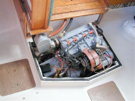
Universal 5411 (11 hp) engine is out of the boat for some work. Cleaning up the engine compartment, replacing hoses, etc.

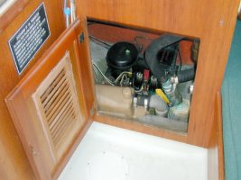
Removed the Vernalift muffler. Was a bit dismayed about the amount of junk I was able to flush and shake out of the muffler. And I think most of it felt like pieces out of the engine exhaust manifold and other internal parts. Putting on a new exhaust manifold and exhaust elbow anyway so I think I'm OK. Are there any "wear" parts internal to the muffler I should worry about and replace the muffler? Externally, it seems almost like new.

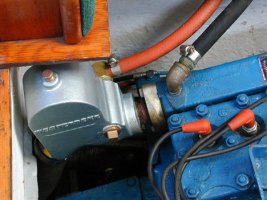
Replacing exhaust hosing. Noted that the engine has a bronze check valve between the exhaust elbow (water injection) and the muffler. Right now the flap is stuck open so it wasn't doing its "check" function anyway.

1st question. How critical is that check valve anyway? I've got to check again but I don't think there is an anti-siphon loop in the exhaust so this may be very important. However, if it's not needed I can eliminate it and some back pressure.

2nd question. Exhaust run between the exhaust elbow and the lift muffler has a 90 degree bronze elbow (plus the check valve) and one from the muffler to the main exhaust run. These will need replacing. What are folks' experience with the fiberglass elbows made by the same company as the Vernalift muffler (Centek)? Are there bronze equivalents? If so, I can't find a source for them. If I install a check valve should I also use the non-metallic one also made by Centek?

Looks like both West Marine and Defender have these Centek parts only as a special order. Any other sources for these components? (OK, that's a 3rd question (or 4th or 5th), enough for tonight.)
 

chaco

Member III
Wet Exhaust Basics

Just replaced and redesigned the entire exhaust system on the mid-engine
E35II. Follow the Vernalift Install Manual (www.centekindustries.com) and
the Westerbeke Engine Install Manual (www.westerbeke.com).
Their are no check valves required in a properly installed exhaust system.
The check valve won't save you from a bad install anyway.
You will see check valves installed in direct wet exhaust systems (no lift can)
Bronze Fittings will not last in the heat prior to the water injection.
I used galvanized steel fittings throughout. You will not live long enough to
justify the cost of fiberglass fittings. The steel system will last 10-20 years if
the exhaust is installed correctly. The stern exit is a Bronze thruhull.
Stainless is a good option on the fittings....could not justify the cost :nerd:

Happy Wet Exhaust :egrin: :egrin:
 

jreddington

Member III
Chaco,

Thanks for the feedback and the link. Should have thought of the Westerbeke site myself. :rolleyes: That install manual was just what I was looking for. None of their diagrams show check valves and the text, while not forbidding them, doesn't seem to endorse them either.

I will go over each of the dimensions outlined in the manual and make sure I've got them right. If so, I don't think I need that check valve after all. And if I don't put in the check valve, I can make a clean run from the injection elbow straight to the inlet of the lift pump with smooth bends in the exhaust hose. The only additional fitting I might need is a reducer from the 2" injection elbow outlet to the 1 5/8" inlet to the vernalift muffler.

Was finally able to get the cap off the check valve today. Had to use a propane torch, tapping, Kroil penetrating fluid (This stuff usually loosens threads right up but this fitting was a challenge), and the biggest pipe wrench in our lab. When I examined the interior there was no sign of the flapper at all. Even if it had deteriorated, I thought I'd find a remnant of it near its pivot point. I suspect a PO added this check valve as a backup and, because of noise or excess backpressure, pulled out the flapper.

As to the bronze fittings, all of these are downstream of the mixing elbow with about a foot of hose before the first fitting. These held up very well except for the threads being seized and almost impossible to bust loose.

Now I just have to track down that 2" to 1 5/8" reducer. Nautical Trader in Nokomis, FL. here I come :egrin:. Should be there by now but my Sunday flight got canceled and could not get rebooked until tomorrow.

Go raibh maith agat arish!!
("Thank you again" in Irish - I'm still in a St. Patrick's day mood)
 

jreddington

Member III
Was down at the boat to confirm my exhaust routing configuration. I do have a loop that comes up to just under the seat in the port lazerette so I think I have a properly protected system, per Westerbeke, without needing a check valve.

So now what I need to do is connect the 2" outlet of the exhaust elbow to the 1 5/8" inlet to the lift muffler. On the old bronze elbow/check valve assembly it appears a sleeve was brazed onto a 1 5/8" elbow enlarging it to 2". Not sure if that was a purchased fitting or made up special for this application. Taking the assembly apart, I've damaged this fitting enough that I wouldn't feel comfortable using it again as a reducer.

What I need is either a straight 2" - 1 58" hose-to-hose coupling reducer, or an elbow reducer. Optimum for neatness would be an elbow reducer. Centek makes one but being fiberglass, it has to be 24" from the elbow. I would only have 10-12" so would need a bronze version. Checked Hamilton Marine. They have a large selection, but not this. Any other sources?

Centek also makes a straight reducer of this size so that may be another option. This size not listed in the Defender catalog, but I'll ask to see what they can price as a special order.

Last option is that Centek makes a Vernalift muffler with a 2" inlet and 1 5/8" outlet. This would let me run a smooth 2" run from the elbow to muffler. May even have enough room to sweep a gradual bend with 2" hose straight from the elbow to the muffler with no other fittings. 1 5/8" muffler outlet keeps me from disturbing the downstream exhaust hose. Will have to e-mail Defender for pricing on this also.

Absolute optimum would be running 2" all the way from exhaust elbow, through muffler and to transom. But this project is already way over budget (just learned I need a new shaft - another $300 Ka-Ching!) and running behind on time. Cetek guidelines say 1 5/8" is good up to 10 hp diesel and mine's 11 hp. I'm thinking that the mostly 1 5/8" system worked before. With taking out the check valve and a smoother exhaust elbow to muffler run, I'm already reducing some backpressure.
 

Loren Beach

O34 - Portland, OR
Senior Moderator
Blogs Author
What I need is either a straight 2" - 1 58" hose-to-hose coupling reducer, or an elbow reducer. Optimum for neatness would be an elbow reducer. Centek makes one but being fiberglass, it has to be 24" from the elbow. I would only have 10-12" so would need a bronze version. Checked Hamilton Marine. They have a large selection, but not this. Any other sources?

Kind of makes one wonder if a local SS fab shop couldn't put this together from two short pieces of 316 tubing... maybe a hour's labor at most.

Do you have a shop anywhere near that fabricates SS brewery tanks and piping? That's the source that has worked well for us in the past.

Well, it was just an idea....
:)

Best,
Loren
 

jreddington

Member III
Update on the project plus additional question

As to one of my original questions on this project, while on the boat this weekend I came across some of the original bluprints for system plumbing on my boat. These prints do show a check valve in the exhaust between the exhaust elbow and the lift muffler, So it does turn out that having the check valve was the original configuration.

However, after reviewing all the Westerbeke and Vernalift design notes, and the fact that I've gone for years without the flapper anyway, I'm going to go without it. I'm Ordering a new Vernalift muffler with a 2" inlet and 1 5/8" outlet (to retain the existing exhaust hose to the stern). I think the radius from the elbow to the lift muffler is wide enough that I can make a smooth bend with 2" exhaust hose.

If not, making that part of the system all 2" makes it easier to find fittings for a bronze elbow. Also, easier to locate fittings for a check valve if I want to put that in later. The original pain was trying to fit all I needed in the run while also transitioning from 2" to 1 5/8". Now that transition will be made by the muffler itself.

Now for the new question:confused: .

As part of the project the shop replaced the exhaust elbow (rotted) with an OEM elbow. The torrensen site shows it as: Part 200266

http://shop.torresen.com/ships_store/index.php?p=details&ident=141264

However, my original elbow had just two fittings. The 2" exhaust, and a 5/8" injection at the top of the elbow. This new elbow has a 2" exhaust, a 5/8" fitting on the lower side, and a 3/8" fitting at the top. Is water injected into the side fitting or into the top fitting? Seems to me you'd want to put water in high to allow for maximum mixing with, and cooling of, the exhaust. Or is that top fitting intended as a vent / siphon break?

I already have a higher loop (to just under the cockpit seats) with vent for the injection water. Normally, seawater coming from the heat exhanger goes up over this loop before going back down to be injected in the elbow. A 1/4" line at the top of the loop bleeds a small amount of this flow out the transom. That does 2 things. The small stream out the transom confirms pressure and water flow from the seawater pump and through the heat exhanger. Second, when the engine is stopped, this line provides the vent to prevent siphoning. No need for a check valve type siphon break which can gum up.

Also, as part of this project, I'm adding a dripless shaft seal which also has a water feed / vent. This should be either vented or provided with a small water flow to prevent air pockets at the seal faces. This keeps the seal from running dry (although you can also cap it and "burb" the system when necessary). If I tee this into the existing bleed/vent line, I get the positive water pressure feed to the seal and a vent when the engine is stopped.

If the fitting on the top of the elbow is a vent, I don't think I'd want to tee this in since that could produce a positive gas pressure which could force exhaust towards the shaft seal, causing an air pocket and running the seal dry.
 

JMCronan

Member II
Jim,

I just replaced my exhaust riser with the same part that you are using.
The water is injected through the side and not through the top. I
checked this by running water through the riser before installation.
The baffling inside the riser allows for proper mixing. Besides being
to small, injecting water into the 3/8in fitting on top would cause
inproper mixing. The 3/8in fitting would allow the water to mix on the
wrong side of the baffling and possibly cause backflow.

Jack
 

jreddington

Member III
JM,

Thanks for the reply. Yes, the 5/8" seems to be the right one. I was just expecting to inject at the top.

Still leaves the question, what do you do with the top fitting? I suspect that with my arrangement, I can just put a brass plug there. Or is there something else supposed to be connected there?
 

JMCronan

Member II
Sounds like you have the same arrangment as mine. I plugged
the top hole and the system works normally. The riser I replaced had
the same setup.

Jack
 

jreddington

Member III
Great,

Thanks,

I suspect that fitting may be used connected to a siphon break if the gooseneck is at least 12" above the water line. I don't think that's the case here. Therefore we need the separate siphon loop to the underside of the cockpit seat.

:egrin:
 

Howard Keiper

Moderator
Sea Quest, a E-35 II, 1972 w/ A-4 has a Westerbeke water injected elbow with antisiphon route for the water that goes up behind the port setee. The exhaust goes aft to a Vetus waterlift muffler mounted transversly just ahead of the reefer compressor unit, thence to a Vetus riser assembly hanging vertically immediately behind the bulkhead, behind the galley sink...the top of which is well above the water line.
Anyway, works great, and has for many years. This is my 2nd elbow, and is 5 yrs old now.

howard keiper
 

Attachments

  • Enclosure mod 4.jpg
    Enclosure mod 4.jpg
    100 KB · Views: 123
  • good elbow.jpg
    good elbow.jpg
    73 KB · Views: 144
  • reefer compress 2.jpg
    reefer compress 2.jpg
    63.8 KB · Views: 156
Top