davisr

Member III
In the month since I have purchased my E25, cb, I have been removing deck hardware for rebedding and have been reworking the centerboard. Concurrently, I have been doing research for some other needed upgrades, one of which concerns the wiring. I have been reading Don Casey's two books, This Old Boat and the Sailboat Maintenance Manual. Both are very helpful. Casey stresses, as do others on this Forum, that it is important to use Type 3 tinned copper wiring. He, and others, have also said that it imperative to use crimped terminals, both for joining wires and for connecting wires to electrical panels.

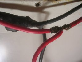
I have two questions, both of which concern the joining of fixtures such as lights and fans in a circuit. Currently, all five house lights (and one fan) are joined in a series circuit. The wire appears to be 16 gauge, Type 2, untinned wire. Each light contains one, #1141, 18 watt incandescent bulb. These lights work sometimes . . . but not all the time. The wire appears to be original. The lights certainly are. I believe the problem is this: the wire is old and the fixtures are joined in a loose fashion (see pictures below). I plan to replace this wire and replace the existing lights with LEDs for the purpose of saving battery power.

Here are my questions:

1. Don Casey emphatically says that one should never wire fixtures in a series, but rather in a parallel circuit. The parallel circuit reduces the resistance that would otherwise be multiplied in the series circuit. What is everyone's experience with these types of circuits on a sailboat, especially in terms of LED fixtures? A parallel circuit would seem to require two or three times the amount of wire, especially since the wires run around the perimeter of the interior of the boat.

2. When joining light fixtures to the positive and negative wires in the circuit, how would you suggest that I make the connections? In a house, of course, one would use a junction box for AC connections. Don Casey does not offer an explanation (at least one that I have found) for this procedure on a sailboat when it comes to DC. One of the pictures below shows the method used during the production process.

Explanation of Images

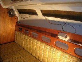
001: Starboard Main Salon House Light, where the circuit begins, then connects with Fan before passing behind bulkhead into Head

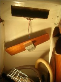
002: Head with its House Light connected to circuit

003: Detail of House Light in Head with bare-wire wrapped connection (with electrical tape removed)


Many thanks Forum members for any help you may offer with this,
Roscoe

E25, cb, Hull 226
 

Attachments

  • E25ElectricPix001.jpg
    E25ElectricPix001.jpg
    95 KB · Views: 64
  • E25ElectricPix002.jpg
    E25ElectricPix002.jpg
    41 KB · Views: 95
  • E25ElectricPix003.jpg
    E25ElectricPix003.jpg
    45.9 KB · Views: 91

Loren Beach

O34 - Portland, OR
Senior Moderator
Blogs Author
Here's an idea...

http://www.ericsonyachts.org/infoexchange/showthread.php?t=2181&referrerid=28

One of the best ways to keep all the wiring straight, behind the fuse/breaker panel, is to have a nearby set of terminal strips. Every wire comes to a separate terminal and circuits you want to control with any one breaker are jumpered at the strip.
If you do a site search on the word Panel, there are quite a few threads that touch on this.

The factory had put several three-way crimp fittings behind our panel and on wire runs to and from it... they were still containing electrons at twenty years, but I wanted it to be more secure and reliable for the future.

I try to maintain a single wire run from each fixture to the main terminal strip. I also added another term. strip in the engine area for several different circuits there.

Cheers,
Loren

ps: if not obvious, every circuit is in parallel
 
Last edited:

Joe

Member II
Just as a point of clarification, your five house fixtures are not joined in a series circuit. They are in a parallel circuit. You have a common positive and ground wire running all the way to the last fixture. The intervening four fixtures just splice off these wires as a matter of convenience. If one fixture fails, the other four will keep on working. In a true series circuit, if one fixture fails, all the fixtures will stop working.

These two wires are effectively acting as extended 35 foot long terminal blocks. :nerd:

What is done more often is to run a common ground wire but individual positive wires to the fixtures. This enables one to have a circuit breaker and/or switch for each fixture in a central place. However, it introduces splicing connections off the common ground. Also, one must ensure that this ground wire is large enough to carry the combined current of the fixtures spliced off it.

The trade-offs become even more difficult when it comes to mast-wiring. Steaming and spreader lights can splice off a common ground wire but this introduces extra connections and therefore points of failure. However, individual ground wires would introduce a lot of extra weight (and cost) to the mast cable. An additional ground wire also just adds another pin to the mast / deck connector -- and one has reduced the total number of connections by exactly nothing.

As far as I can tell, there is no consensus of opinion on this matter. Using a common ground wire is perfectly acceptable. I'm personally running individual ground wires, but I'll be hard pressed to justify it, other than knowing that I don't have a common ground that can cause multiple fixtures to fail and that I've minimized splicing connections.
 

davisr

Member III
Loren and Joe,

Thank you for your helpful replies. Yes, I see what you are saying Joe. I do indeed have a parallel circuit at present. I should have recognized this, since, at present, one non-working light, or two non-working lights do not doom the entire circuit.

Loren, I have read back through Don Casey's Sailboat Maintenance Manual and have seen that he does in fact talk about terminal strips. He writes, "terminal strips are superior to three-way connectors for wiring several appliances to the same circuit. A terminal strip/fuse block combination allows you to protect each appliance independently and have all fuses in an accessible location," (p. 471). He doesn't say much more than this.

So, from what I gather from Casey's diagram and from your explanations, Loren and Joe, I have four options for the rewiring of the five cabin lights (or any such replacement lights such as LEDs) and the fan (or any additional fans):<?xml:namespace prefix = o ns = "urn:schemas-microsoft-com:oops:ffice:oops:ffice" /><o:p></o:p>
<o:p></o:p>
1. Rewire lights and fans in exactly the same way they are now wired - in a parallel circuit with each fixture spliced (and taped with electrical tape) onto a common positive and common ground that run around the perimeter of the interior of the boat. Cheapest in price, but most likely to cause problems (due to corrosion)
<o:p></o:p>
2. Rewire lights and fans in exactly the same way they are now wired - but instead of splicing and taping each fixture onto the common positive and common ground, join fixtures to the common positive and common ground with three-way connectors. A little more money than option 1, but less likely to corrode.

3. Rewire lights and fans with a common ground running around the perimeter of the interior of the boat. Ground fixtures by joining them to common ground with three-way connectors. Individual positive lines would then be run from each fixture to a single terminal strip. Terminal strip would then be connected to single fuse or breaker on main panel. Thus, one switch on panel would control entire circuit. At the same time individual switches for each fixture could be wired from individual terminals on the terminal strip. More money than option 2 (due to the extra wire and the terminal strip) but more flexibility, since each fixture has its own switch - sort of like what you'd see in a house with a set of switches near a entryway door.

4. Rewire lights and fans as in option 3, but instead of using a common ground, use individual grounds and positives for each fixture. All grounds and positives would be led to the terminal strip, which would itself be connected to a single fuse or breaker on the main panel. As in option 3, each fixture could have its own switch wired off of the individual terminals on the terminal strip. Even more money than option 3 (due to the extra ground wires). Just as flexible as option 3, since each fixture has its own switch, but more security since each fixture is complete separate from the next.

Do these scenarios appear to be correct as I have sketched them?

Thanks again for all your help,
Roscoe


Joe

Member II
I vote for option 2 because these wires are easily accessible. The original wiring diagram also shows the same common ground used for the navigation lights. The wire colors are:

common ground: black
cabin lights: red
navigation lights: white

They correspond to the top and middle switches on the original control panel.
 

davisr

Member III
Thanks Joe,

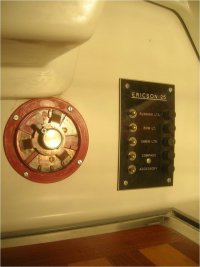
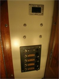
I'm leaning towards option 2 as well, if only because of its simplicity. The wiring colors you mention correspond to the scheme in my boat. Same goes for the main DC panel. I have included a picture of it, as well as a picture of the other panel under the companionway ladder. Does your E25 have one of these as well?

Roscoe
 

Attachments

  • E25ElectricPix004.jpg
    E25ElectricPix004.jpg
    38.9 KB · Views: 61
  • E25ElectricPix005.jpg
    E25ElectricPix005.jpg
    37.8 KB · Views: 54

Joe

Member II
I only have the panel next to the rotary battery switch.

The positions are used as follows:

Running lts - Running Lights - white
Bow lt -Steaming Light - brown
Cabin lts - Cabin Lights - red
Compass - Spreader Lights - yellow
Acc - Masthead Light - blue
 

Tom Metzger

Sustaining Partner
I've had bad luck with three way crimp connectors. I've never used them, but I have had problems with them installed by others. I think that they moved the terminals while installing which loosened the rivets.

What I have used done is gone to the next larger size connector and put two wires in the same crimp on a butt splice or a ring terminal. With three wires in a butt splice I will strip a longer section on the single wire and fold it double to fill the connector.

Another simple option is to use three ring terminals with a machine screw. Make the crimps before screwing them together to avoid the same problem as the three way splices.

Care must be used to avoid short circuits when using this or other methods. If several circuits are involved spend the bucks for a terminal strip.
 

davisr

Member III
Thanks, Tom, for your advice about the three-way connectors and the option of using three-wire butt-connector method. I have not heard of that. It looks to be the case, then, that you would suggest I folllow option 4 described in my posting above. I do, in fact, have numerous different circuits to consider as is evidenced by the two different DC panels in the galley/companionway area.

I have a follow-up question, though, regarding the use of terminal strips. If the terminal strip has, for instance, 12 different connection posts and I use 7 of them for cabin lights and fans, I assume I can use the other 5 posts for other purposes. From what I can tell from Loren's photo and from pictures in the West Marine catalogue of the Blue Sea Systems terminal strips, the 7 cabin lights and fans would be connected to 7 of the posts on one side of the strip. A wire on the other side of the strip would then connect these 7 posts to a single breaker on the main panel. This would leave the remaining 5 posts open for another purpose, right? It all comes down to choosing how many posts I want to dedicate to a single breaker on the main panel, right?

Thanks, fellas, for your continuing help with this.

Roscoe
 

Tom Metzger

Sustaining Partner
Roscoe - There is no reason to run a separate pair of wires to each lamp. If your lamps have pigtails just crimp them to the 12v pair that you run around the boat. The only reason to run a bundle of wires is if the loads require separate fuses or breakers. Five lamps and two fans will not be a problem on a single fuse.

If the lamps are in different directions from the panel then run two strings.

The idea is to keep it simple. :)
 

davisr

Member III
Thanks for getting back in touch Loren, Joe, and Tom. I certainly want to keep things as simple (and affordable) as possible, and I can see the beauty of simply splicing the pigtails of the lamps and fans to the two wires that run around the perimeter of the boat. This is the way the boat is presently wired. I would only alter it so that the pigtails join the main wires either with three-way connectors, or with a modified version of this such as you have suggested, e.g., three terminal rings joined by a machine screw, or three wires joined with a butt connector (as you describe above). Any of these techniques would would essentially fall into option 2 listed in my posting above.

Since, however, we have gotten onto the subject of terminal strips, I am interested in more fully understanding their benefits, aside from the fact that they make the boat more orderly, and thus more user-friendly, and ultimately, more safe. Loren, I have looked around on other websites and at the postings on this forum under the heading of PANEL, and have not found a lot of information (it's very possible that I didn't read the correct PANEL postings). At any rate, as I have understood it from our conversations, the benefit of avoiding options 1 or 2 (described in my above posting), it that corrosion problems can more readily be avoided. Thus, Tom's suggestion is that if one must choose option 2, then one should use the three-terminal ring or three-wire butt connector techinique, since these will inhibit corrosion problems.

So . . . moving on to the issue of using a terminal strips for accepting a pair of wires run separately from each lamp and each fan (option 4 described above). Isn't it the case that in a situation like this, the benefit of running separate wires from each lamp and fan is that each fixture is isolated and thus protected from the other? Likewise there are fewer possibilities for corrosion along a common ground. At the same time, another benefit is that you don't have to have a gigantic main panel with switches/breakers for all of these separate fixtures because you can put them all on a single switch/breaker. How? By running all the separate lamp and fan wires to the terminal strip, and then running a single wire from that strip to one breaker on the main panel.

Does it sound like I'm on the right track with this?

Thanks, as always, Forum members for your help,
Roscoe
 

Loren Beach

O34 - Portland, OR
Senior Moderator
Blogs Author
So . . . moving on to the issue of using a terminal strips for accepting a pair of wires run separately from each lamp and each fan (option 4 described above). Isn't it the case that in a situation like this, the benefit of running separate wires from each lamp and fan is that each fixture is isolated and thus protected from the other? Likewise there are fewer possibilities for corrosion along a common ground. At the same time, another benefit is that you don't have to have a gigantic main panel with switches/breakers for all of these separate fixtures because you can put them all on a single switch/breaker. How? By running all the separate lamp and fan wires to the terminal strip, and then running a single wire from that strip to one breaker on the main panel.

Does it sound like I'm on the right track with this?

Thanks, as always, Forum members for your help,
Roscoe

I do not understand the part about isolating the fixtures, and corrosion will depend on how much moisture you allow inside the boat.
The terminal strip lets you bring each device wire to a separate terminal and use the provided metal bridges to join several terminals together, and then just bring one wire to the breaker on the panel (which is what I did) for that group of related devices.

I have seen newer production boats where they even economize on breakers by having some sorta-kinda related circuits come to small on-off switches and then have several of those switches go to one breaker. That's actually not such a bad idea, because then you can isolate circuits for work with inexpensive switches and the breaker still serves to guard against a short in the wiring. (This was on a Catalina 28.)

Loren
 
Top