AC Outlet Wire termination

Nick J

Sustaining Member
Moderator
Blogs Author
There seems to be very little information about this and nothing seems to fit together properly but most boats have shore power and outlets, so What does everyone else do?

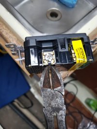
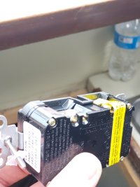
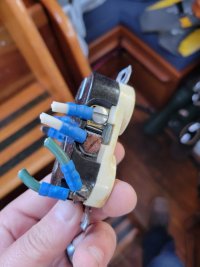
I replaced my shower mixing valve which naturally lead to rewiring and replacing all my AC wall outlets (Will post about this later). Ericson used crimp fork connectors. The screw to crimp connector held up well and were tight on my '84 specimen, but there's a few things I would like to improve. Namely, using heat shrink flanged fork connectors. The problem is on all modern outlets I've found, there's a small piece of plastic inhibiting the fork connector from being used. On my previous boat, I clipped this off, but as I'm starting this project again I wanted to check with eveyrone else. There has to be a better way and/or products to make this work.

Pictures from the previous boat (I couldn't find heat shrink connectors at the time)
20191201_094038.jpg
20191201_103653.jpg
20191201_103715.jpg
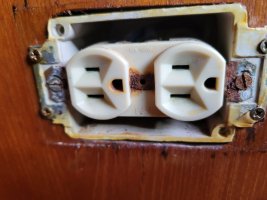
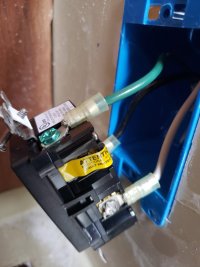
Current boat and reason for replacing the outlet:


20230729_180759.jpg
 

Kenneth K

1985 32-3, Puget Sound
Blogs Author
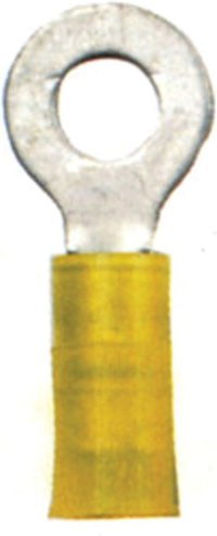
Yeah, I'd clip off that blocking post and move on with the forked connectors. You could also try ring connectors IF the screws on the receptacle back out all the way. Often, I forego heat-shrink terminals for the old-fashioned ones. Then I add liquid elec tape to the open end and cover the wire and terminal with shrink tubing--this is more work though. The old (non-heat shrink) terminals seem to have a larger crimp body and look like they'd be more secure on larger gauge wires.

Note: The only actual AC wiring I've redone on my boat to this point are the AC leads to the battery charger.

heat shrink.jpg Shrink old.jpgOrig.
 
Last edited:

gareth harris

Sustaining Member
Pictures from the previous boat (I couldn't find heat shrink connectors at the time)

View attachment 47745
From the photograph that looks like it is designed for the bare wire to be wrapped around it, lifting up the copper piece under the screw - I could be wrong without pulling it apart but that is how many AC components are designed.

It is much cheaper to buy heat shrink in tubular sections, cut them to length, and cover the gap that way.

Gareth
Freyja E35 #241 1972
 

Nick J

Sustaining Member
Moderator
Blogs Author
From the photograph that looks like it is designed for the bare wire to be wrapped around it, lifting up the copper piece under the screw - I could be wrong without pulling it apart but that is how many AC components are designed.

It is much cheaper to buy heat shrink in tubular sections, cut them to length, and cover the gap that way.

Gareth
Freyja E35 #241 1972
Yes, that's the crux of the problem. All outlets I've found are designed to be used with solid coper wire, not the stranded stuff we use on our boats. The connections very slightly between directly wrapping the wire around the screw or inserting in a hole and the screw tightening a backing plate against the buss pinching the wire. Both designs aren't ideal for stranded wire and they don't seem to accept a connector without modification like I've showed above. I'm hoping someone on here has experience with a better outlet design or at least confirmation that they're doing the same modification to allow fork terminals to fit.
 

gareth harris

Sustaining Member
It is standard procedure to wrap stranded wire around terminals - solid wire is usually just used for communications. The problem on a boat is preventing exposed strands from turning green and creating resistance at the connection, and if you can work out how to a terminal into the system then it would certainly help.
 

Cutbait61

Member II
Ferrule Crimping Tools Wire Pliers - 1800 PCS Wire Ferrules with Crimpers Pliers Kit for Electricians, Adjustable Ratchet Tools with Terminals Connectors AWG 28-7, 0.08-10mm²
Suggestion...check out the above..
The method prescribed above is a more desired result when terminating stranded wire. The ferrules are crimped directly to the conductor and by design are suited for compression/mechanical termination points , eliminating loose strands etc. and the need to modify the device they are being terminated to. The use and application of ferrule terminations for stranded wire is an industry standard in nuclear plants and petro-chem facilities , of which I inspect the electrical systems and their installation daily.
In the photo , what appears to be a GFCI receptacle, the terminals are designed for solid wire /mechanical compression for contact. The ferrule method used for stranded wire in effect satisfies the criteria for a sound electrical connection.
Ferrule kit w /crimper found on Amazon
 

Nick J

Sustaining Member
Moderator
Blogs Author
I have a similar kit and use it for control wiring (NMEA 0183, Tank monitors etc). My hesitation on using it for 120 vac is ABYC's standard about terminals needing to be ring or captive spade type. It probably isn't too big of a risk, but if a loose wire is going to cause damage, it's going to be on the AC side.

Are wire terminations in nuclear plants and petro-chem facilities exposed to vibrations? I've found equipment made for use in the railroad industry are a good fit for marine use because they can be used close enough to tracks to experience some heavy vibrations. The DIN rail terminal block with captive threaded posts I used in my DC panel rewire project are designed for the railroad and they worked out really well.
 

Cutbait61

Member II
Vibration conditions..absolutely!!..safety related terminations in a nuclear plant must be seismically qualified by the vendor. Safety related meaning the safe shut down of the reactor and associated systems..refineries are the same if not more vibration conditions , due to the nature of the environment.
A threaded stud type termination and the use of a ring lug is definitely a tried and true method..but you shouldn't have to modify a component or end device to achieve its application end use..
If AYBC standards dictate spade/ring lug terminations on 120v A/C systems then a GFCI breaker at the distribution panel , ahead of the receptacles is another method to obtain GFCI protection for the entire circuit feeding the receptacles instead of individual GFCI receptacles and would allow the use of standard duplex receptacles which will allow use of spade/ring lugs without modification of the end device.
 

Cutbait61

Member II
The spade lug method of termination is perfectly acceptable, however ,the example you show is not in conformance with the NEC according to Article 300
13 (B) /..Mechanical and Electrical Continuity..
(B) Device Removal ..states in part..
the continuity of a grounded conductor (neutral) SHALL NOT depend on device connections such as lamp holders, receptacles and so forth ,where the removal of such devices would interrupt the continuity. ..in other words..
Grounded conductors (neutrals) of branch circuits supplying receptacles, lampholders or other devices are not permitted to depend on terminal connections for continuity between devices..a splice of a jumper from the branch circuit to the device is permitted...this method allows replacement of the device without interrupting continuity of energized downstream loads..and in the event of device failure other receptacles downstream would not be interrupted..
The preferred method is to "pigtail" a jumper for the hot (ungrounded conductor)..neutral (grounded conductor) and the grounding conductor (equipment ground/green)...
The device would then only have 3 conductors terminated to it..H..N..G
Lastly...as anything else..devices /receptacles fail for a multitude of reasons...I can't count the number of service calls I've been on where several outlets were "dead" but testing ( hot to ground )proved otherwise and it was always a device upstream that had failed and interrupted continuity of the neutral to other receptacles due to using the device to provide continuity...
I will also add the potential exists for the equipment ground to be interrupted in the event of device failure leaving outlets downstream unprotected..which can be a deadly condition.
 

Nick J

Sustaining Member
Moderator
Blogs Author
I hadn't thought about the safety issue with daisy chaining the ground, but that's a really good point. I have some heat shrink step down butt connecters I can use to create a pigtail.
 

Cutbait61

Member II
I personally would go with wire nuts and possibly a piece of shrink tube over each splice/wire nut to provide extra protection due to the harsh /wet environment...thats just me... hopefully I've been able to help you.
 

Nick J

Sustaining Member
Moderator
Blogs Author
Absolutely! The continuous ground reminder is great advice and definitely something form home and industrial wiring that can and should apply to boats. Wire nuts, on the other hand, have no place on boats.
 

Cutbait61

Member II
I agree with you 99.9% in regards to using wire nuts..I base my call to use them on 43 years of knowledge and experience in the electrical trade/field..I would never suggest using that method to connect critical equipment or "safety related" systems associated with the safe operation of the vessel..of which they all are..IMO...however a general purpose 120 volt outlet is only in use while on shore power , at least in my case because I have no onboard generator to utilize them while underway...and the factory installed boxes used for the receptacles are generic Romex /residential type boxes which are not meant to be used in wet locations...once again that's just me....good luck on your project ..im currently installing a 100 watt solar panel to keep the batteries charged..
 

Nick J

Sustaining Member
Moderator
Blogs Author
I finished up the AC wiring for now. I still want to replace the section from the main panel to the first outlet, but I decided to wait because there's a tricky section above the panel cabinet that has the potential to take a lot of time and we're leaving next weekend to explore the Gulf islands.

I ended up using TR industrial grade Eaton Decorator outlets. These were the only ones I could find that didn't have the blocking post protruding above the terminal buss which allowed for the use of flanged spade terminals. After giving the non interrupted ground configuration Cutbait mentioned above some thought and trying a few different types of reducing butt connectors a try, I decided to just use two spade connectors instead. Although I think the idea is solid and valid for most use cases, on my boat where there's just a single AC circuit, anytime I'm working on the circuit, the breaker will be open so there won't be too big of a risk of shock where a non continues ground would produce a risk. The connection with two stacked flanged spade terminals on the ground screw created a more secure and water resistant connection than any of the butt connectors I tried. It's a little tricky to get them to seat properly due to the flange, but if you offset them by apx. 30 degrees, they sit flat, create a good connection, and do not interfere with each other. Of course, I forgot to take pictures.

On two of the electrical boxes, the screw for the outlet broke off due to substantial rust. I had to replace the box and new electrical boxes are not the exact same size as the old ones. The multi tool came in handy slightly lengthen the opening, but there is about a 1/8" gap between the edged of the box and the opening on both side in width.

If I had to do this again, I'd find a source for hospital grade outlets. I don't have any experience with them, but I've read they use higher quality material and are designed to last longer. They are 3x more expensive, but if you're only don't a handful of outlets they look to be worth it.

It would be great to keep this conversation going with anyone else who's doing work on their shore power system providing info on what they did. I think my solution has some room for improvement, but I'm positive it's better than where I started with 100% tinned copper wiring and terminals now and sealed connections. If the outlets go bad, it won't be a gut and replace project, just a simple outlet replacement.
 

mjsouleman

Sustaining Member
Moderator
I hate playing with electricity, BUT I really need to replace outlets through out Discovery.

I got lost in the conversation, can I get recommendations for outlets, connectors, and flange/ring connectors.
 

Nick J

Sustaining Member
Moderator
Blogs Author
I'm not an electrician (industrial, marine, or home) and I'm not an expert on ABYC standards. I try to research from known sources (MarineHowTo.com, Nigel Calder books, etc) and apply what I've read. What I've found is most people I've hired and factory installs do not meet the standards I've read about, so I'm apprehensive to have "professionals" work on my boat which is one of the reasons I do most think myself (the other being cost). With that disclaimer out of the way, here's what I recommend:

Wire: 12 AWG triplex marine tinned stranded (for distribution circuits only, use 10 AWG for main feed from the plug to panel)- https://www.amazon.com/Ancor-131310...t=&hvlocphy=9033382&hvtargid=pla-556505896237

Connectors: Anchor 10-12 #8 flanged spade connectors: https://www.amazon.com/Ancor-Marine-Grade-Shrink-Terminals/dp/B000NI3BK0?th=1
(I'm not convinced these are the best out there. The crimp part is not a continuous (welded or brazed together), but I haven't found ones that are. I've tested these in my garage with weights and, combined with my crimper, they seem to be good enough)

Crimper: MarineHowTo.com used to sell afordabloe (apx. $60) crimpers with jaws for heat shrink terminals. I purchased one of these and it's been good. They are uncomfortable to use, but the results are good. I can't seem to find them on the site anymore. Rod does have an amazon link where you can find other crimpers he recommends: https://www.amazon.com/shop/marinehowto

Outlets: This is where I was looking for the most advice and haven't found the perfect outlet yet. What I'm looking for is an outlet with terminal screws that can either accept ring terminals (ideal) or flanged spade connectors, high quality, and resists water or moist environments. The outlets I chose were 15 amp industrial tamper resistant Leviton outlets form Lowes:
I think these are it: https://www.lowes.com/pd/Eaton-Arro...ZlXVsVHmuzlg6QavfxMaAr0dEALw_wcB&gclsrc=aw.ds

If I had to do it over, I would look at hospital grade outlets like this:
(I haven't seen these in person, so I don't know if there's a blocking post or any other problem prohibiting using a space terminal.

Panel: My boat came from the previous owner with a BlueSea systems 8 position panel, so I kept it. If I was starting from scratch or replacing the original panel, I would get one with an amp meter and ELCI breaker like this: https://www.amazon.com/ELCI-Main-Do...9718&s=hi&sprefix=elci+panel,tools,152&sr=1-3 Note that this one comes with a volt meter, but I would change it out for the more functional amp meter. As mentioned quite a few times on the forum for DC systems, use of remote terminal strips to consolidate the neutral and ground buss is highly recommended as opposed to bringing everything to the back of these panels.

Galvanic isolator: I chose to go the inexpensive route with this one: https://www.emarineinc.com/Yandina-Galvanic-Isolator (to ensure it's operating safely, I test it frequently to ensure the diodes haven't failed creating an open circuit to ground)
If you don't want to test frequently, you can go with one that indicates failure like this:

Shore Power Plug: Probably the most important part of the shore power system. Even if your plug is brand new, replace it with a smart plug:
https://www.amazon.com/dp/B008JH1TG...HHPI90L&ref_=aip_sf_list_spv_ofs_mixed_d_asin. MarineHowTo goes into great detail on why this is so important.

Again, this is just rambling from a fellow boat owner, so it's worth what you pay for it. Hopefully others will chime in with their experience and offer up some good alternative (and hopefully even better) products.
 

southofvictor

Member III
Blogs Author
Also, my existing SP goes to the AC main breaker on the OEM Ericson distribution panel, then to the inverter/charger, then back to the panel for distribution. I assume
this is because the inverter pre-dates good pass-through functionality? Any other reason you can think of?

The instructions on my new one say it should be wired directly from the sp inlet with an ELCI breaker at the inlet to protect swimmers plus another at the panel to protect the boat. It’s a Victron Multiplus 12/2000/80, not installed yet.
 

Nick J

Sustaining Member
Moderator
Blogs Author
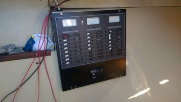
I mounted one in my 25+ when I added shore power, but I haven't put one in the 35-3 yet. On the 25+, I found a Blue Sea Systems panel with DC and AC on clearnace. It was way more than the 25+ needed, but it was cheaper than replacing the breakers in the original panel. I just replaced the main breaker with the 3 position ELCI (see the top of the far right bank of breakers):
IMAG1418.jpg

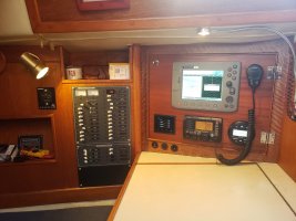
I can do the same on my 35-3 since it has a newer Blue Sea Systems panel with enough room:

20210513_182740 (1).jpg

If you don't have room on your panel, Smart Plug offers a main ELCE breaker you can mount next to your plug:


You can also add a dedicated main circuit brekaer panel:

 
Top