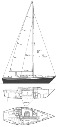
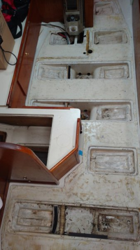
30+ Mast Compression Post/Bulkhead Repair Ideas

bigd14

Contributing Partner
Blogs Author
Since I discovered a big leak through the mast step this winter I have been wondering if I should address the slight compression in the area underneath the mast step. With a haulout and mast unstep scheduled in a couple weeks I am starting to think more seriously about it.

I don't have any photos with the step removed, but there is a slight depression or divot in the cabin top under the starboard aft quarter of the step and mast plate. The underlying material felt sound 5 years ago.
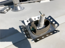
1682626996708.png

I suspect that water was getting in through the wiring hole for years before I got the boat and rotted a small portion of the bulkhead underneath. The bulkead then slowly deformed under pressure from the mast and lead to the deck compressing in that area. The photo below shows the compression of the bulkhead with some of the plywood that has deformed and delaminated (photo is from the head compartment on the starboard side of the compression post looking forward and towards the port side of the boat). Just to the right outside the photo is sound bulkhead and tabbing (only about an inch of tabbing has been compromised). The compression post appears sound.
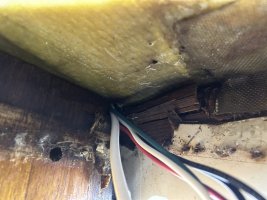
IMG_1016.jpeg

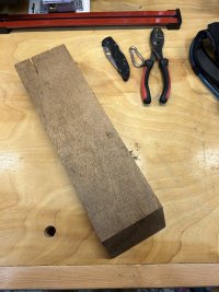
So what to do? Easiest of course would be nothing, which may be a valid approach as I am not sure how much further the damage can or will progress. But with the mast down I have an opportunity to jack the deck up and make repairs (the deck won't move much due to the tabbing on the bulkhead). To support the deck in that corner a thick block of teak or something could be attached through the bulkhead and maybe extended over to the compression post as well. This at least might help prevent any further deformation. The wiring bundle is going to be removed and the area sealed completely from the top. I am hoping I will not have to replace the core material under the step but that is possible if it looks like the divot has gotten worse or the step area feels spongy. I am also hoping to avoid overthinking things (my normal modus operandi) as I'm worried I could easily manage to turn this into a major project when a simpler option exists.

Thoughts and opinions welcome.

Thank you.

Doug
 

Frank Langer

1984 Ericson 30+, Nanaimo, BC
That area on my boat was reinforced by a previous owner with a metal plate, likely aluminum, about 6 inches long, 4 inches wide and 1/8 inch thick, I think. It is placed on the underside of the deck on top of the compression post. There is no sign of prior leaks or damage, so this might have just been preventative, or perhaps even factory.
Frank
 

Dave G.

1984 E30+ Ludington, MI
The compression post appears sound.
Possibly because the mast plate is much larger footprint than the mast itself ? There would be a lot of leverage at the corners of that plate as the mast moves ever so slightly side to side, front to back. The compression post o.d. is pretty small compared to that plate. Mine does not have the metal reinforcement plate that Frank has but I do not have a mast base plate either. Is the fiberglass/core solid ? I would check that very closely. If it It's good would measure everything, make notes and keep an eye on it for a while. If it's spongy you will have your answer.
 

tenders

Innocent Bystander
The wires penetrating the overhead was a rare poor design decision on Ericson’s part. Your core under the mast is probably plywood snd is probably de-plying and rotting. It is fixable, though it is a messy fix, made more complicated by the camber in the deck surface. I don’t know if your situation needs to be fixed right now, but if you’ve already got the mast down….

Here’s how I did it.


Solarken

Member II
There is a prescribed method that calls for adding a ¼” aluminum plate and more to the starboard side of the post. It can be done in water without removing the spar.
 

Vickigehrke

Member I
Ours had the same- slight depression, we opened the ceiling, dried out the wood (which was still sold), coated it with epoxy, stopped the leak and our consultant recommended an additional post alongside the head doorway post. Our mast is offset, 32-2.
Best wishes,
Vicki
 

bigd14

Contributing Partner
Blogs Author
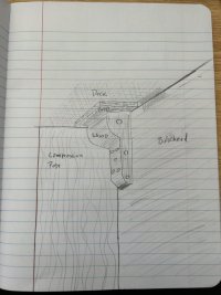
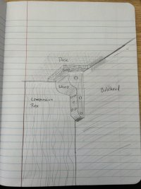
Thanks all, good solutions. I like the idea of a plate between the compression post and deck but I'm not sure if I would be able to jack the deck up enough to fit one. These ideas got me thinking about how I might be able to buttress that area without an additional post running to the sole. I found a nice piece of mahogany in my scrap wood stockpile. I could craft it into a type of corbel that attaches to both the sound part of the bulkhead and the compression post with bolts. I would first epoxy a G10 block to the underside of the deck area to provide a larger bearing surface, then lightly jack the corbel/G10/deck sandwich up and drill and fasten into place. Of course this doesn't address the rotting (?) plywood in the deck above, but at least more of the bearing surface underneath the deck would be supported and the area shouldn't deteriorate any further.

Tenders, I read your linked repair post prior and am hoping to avoid such an extensive surgery, but the "while you are in there" syndrome is top of mind right now. I recall that it appeared to be marine plywood under the step last time I had the mast out, so I am sure you are correct about the rot and delamination. I have limited time in the yard so I'll have to assess that when the mast is out.

IMG_1793.jpeg
IMG_1794.jpeg
 

tenders

Innocent Bystander
Thank you for adding "corbel" to my vocabulary! This is certainly not my area of expertise, but based on the length of the sidestay and fore/backstay chainplates, and the number of fasteners tying them into the bulkhead/hull, I would be very careful to make sure the corbel was similarly attached. The forces from all of those shrouds are pushing down the foot of the mast.

The plate modification, and corbel which you drew so skillfully, are intended to address the offset betwixt the compression post and the mast, and the lack of support for the foot of the compression post, which for whatever reason wasn't placed on top of the keel. With the mast down, you will be amazed, I think, at how far you can jack the overhead up above the compression post and bulkhead with a $20 Harbor Freight bottle jack and a piece of 2x4. Or even a car jack. The only trick to doing that is establishing a level surface for the jack so all the forces remain in column.

The rotting wood and unstable surface directly below the mast is another matter. If the mast is situated on an inch or more of sponge, it doesn't matter where the compression post is.
 

Dave G.

1984 E30+ Ludington, MI
1682772448435.pngBigd is this the bulkhead area inside the head ? On mine that is made of pretty thin material maybe 1/4" at best. If yours is the same you may want to attach the corbel directly to the compression post ?
 

bigd14

Contributing Partner
Blogs Author
Bigd is this the bulkhead area inside the head ? On mine that is made of pretty thin material maybe 1/4" at best. If yours is the same you may want to attach the corbel directly to the compression post ?
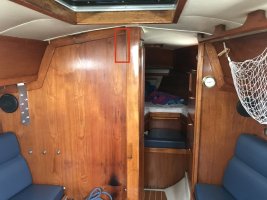
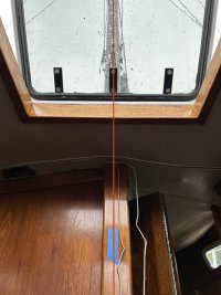
Thanks for pointing that out Dave. Yes it is the bulkhead between the head and the main cabin. I have been assuming it is 1/2”plywood and adds significant strength to the area but I will double check. It would be easy enough to attach the corbel to the post.

The support would be placed behind the bulkhead in the head compartment about in the area marked in red below.

IMG_6900.jpeg
 

bigd14

Contributing Partner
Blogs Author
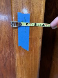
I did some investigating and measuring of the compression post and thought I would post this for posterity's sake. The post is basically a big mahogany (maybe teak?) board approximately 1 3/4 inches thick and about 11 inches wide (fore and aft). There are some trim pieces along the aft edge to hide the folding door betweek the salon and v-berth and some additional solid blocking around the cabin top to help support the deck a bit.

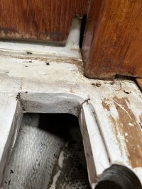
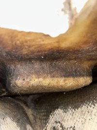
The compression post appears to be a little offset from the centerline of the mast to stbd. The bottom of it is held in a small pocket molded into the top of tri-axial force grid. I was surprised to find that there was not a connection between the TAFG and the keel or hull under the mast. It became obvious why when I realized that the mast is actually at the very front of the keel. There is a big pad of fiberglass or some material that juts below the TAFG which I found strange and still haven't figured out what it's purpose is. The TAFG is about an inch and half thick in this area to support the loads.

I hope this might help someone understand the construction of this area if needed in the future.

Centerline offset slightly (kind of hard to tell from photo)
IMG_1850.jpeg

Aft trim piece hides post. Total width is to the dotted line, green dot is centerline as best as I could tell.
IMG_1868.jpeg

The TAFG is super robust under the post.
IMG_1867.jpeg

This is the weird pad under the post. I don't think the post extends much below the top of the TAFG in the photo above but it's hard to tell. It's not connected to anything, you can feel all around it.
IMG_1866.jpeg

1683330873082.png
 

Nick J

Sustaining Member
Moderator
Blogs Author
I did some investigating and measuring of the compression post and thought I would post this for posterity's sake. The post is basically a big mahogany (maybe teak?) board approximately 1 3/4 inches thick and about 11 inches wide (fore and aft). There are some trim pieces along the aft edge to hide the folding door betweek the salon and v-berth and some additional solid blocking around the cabin top to help support the deck a bit.

The compression post appears to be a little offset from the centerline of the mast to stbd. The bottom of it is held in a small pocket molded into the top of tri-axial force grid. I was surprised to find that there was not a connection between the TAFG and the keel or hull under the mast. It became obvious why when I realized that the mast is actually at the very front of the keel. There is a big pad of fiberglass or some material that juts below the TAFG which I found strange and still haven't figured out what it's purpose is. The TAFG is about an inch and half thick in this area to support the loads.

I hope this might help someone understand the construction of this area if needed in the future.

Centerline offset slightly (kind of hard to tell from photo)
View attachment 46953

Aft trim piece hides post. Total width is to the dotted line, green dot is centerline as best as I could tell.
View attachment 46954

The TAFG is super robust under the post.
View attachment 46955

This is the weird pad under the post. I don't think the post extends much below the top of the TAFG in the photo above but it's hard to tell. It's not connected to anything, you can feel all around it.
View attachment 46956

View attachment 46957
This looks like a non TAFG model. Do you have any pictures of the bilge or areas under the settes?

My non TAFG 1980 25+ looked like yours, but it had a block of wood between the cabin sole and keel. Yours doesn't seem to have ever had a block. Is the structure below the compression base sturdy enough to take the compression load? Is the sole sagging or showing any other signs of stress?
 

Frank Langer

1984 Ericson 30+, Nanaimo, BC
This looks like a non TAFG model. Do you have any pictures of the bilge or areas under the settes?

My non TAFG 1980 25+ looked like yours, but it had a block of wood between the cabin sole and keel. Yours doesn't seem to have ever had a block. Is the structure below the compression base sturdy enough to take the compression load? Is the sole sagging or showing any other signs of stress?
The E30+ has a partial TAFG, not as widespread as later Ericson boats, but still pretty solid. I got this info from Seth, who used to work at the Ericson factory. The TAFG is also mentioned on the E30+ sales brochure.
Frank
 

bigd14

Contributing Partner
Blogs Author
This looks like a non TAFG model. Do you have any pictures of the bilge or areas under the settes?

My non TAFG 1980 25+ looked like yours, but it had a block of wood between the cabin sole and keel. Yours doesn't seem to have ever had a block. Is the structure below the compression base sturdy enough to take the compression load? Is the sole sagging or showing any other signs of stress?
It's definitely got the TAFG. https://ericsonyachts.org/ie/threads/e30-tafg-structure.14448/ It doesn't look like any sagging or stress except for some very slight gelcoat cracks in the head area sole (no pics). The structure seems very strong. I don't think there is a problem down there, I was just trying to understand how the boat was put together and the forces at work beneath the mast.
 

Nick J

Sustaining Member
Moderator
Blogs Author
Does it stop short of the compression post base or is the structure in the picture part of the TAFG? It's pretty cool to see the evolution if the TAFG across the different models and production years. Ericson must have spent a fortune in molds with all the changes.
 

Nick J

Sustaining Member
Moderator
Blogs Author
Yup, that's pretty definitive! Must be some stout layup around that area to support the compression post without structure directly below. Way better design than the early pre TAFG 25+.
 
Top