• Untitled Document

    Join us on April 26th, 7pm EST

    for the CBEC Virtual Meeting

    All EYO members and followers are welcome to join the fun and get to know the guest speaker!

    See the link below for login credentials and join us!

    April Meeting Info

    (dismiss this notice by hitting 'X', upper right)

E35/3 electrical panel difficult

gabosifat

Member III
Hi All,

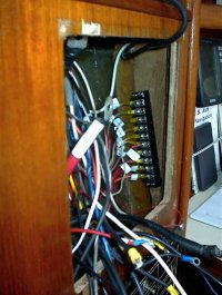
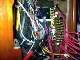
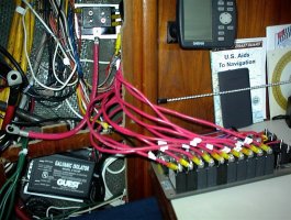
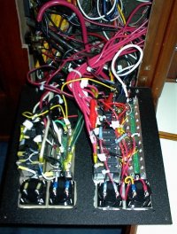
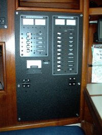
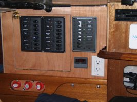
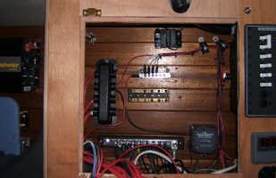
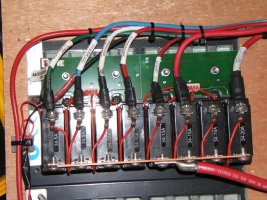
I've been doing a bit of rewiring on my boat but am really surprised how difficult it is to get electrical connections onto the hot side of the breakers. All of the wires on my boat are fitted with the flat connectors with the hole rather than spade fittings. This means that you have to remove the screw completely from the breaker to put on a new wire - this requires a short stubby screwdriver (used sideways) and yes the screw inevitably falls down into the channel (like 3 or 4 times). I would like to redo the whole panel and would change all the connectors to spades so the screw doesn't have to be removed. I know these are not as reliable and the wire can pop off if the screw loosens. I looked at a friends Pearson 36 panel the other day & it's like a dream compared to the Ericson - every terminal is easily accessible & right there in front of you. On my Ericson panel the wires look like one big tumbleweed ball!!

On the same vein, has anyone hinged their panel so it's easily accessible rather than rely on the 4 screws?

Would appreciate any advice and particularly any pictures if anyone has done a rewiring job on their panel. I'm not sure how a stock Ericson wiring job looks as I'm sure with a 20 year old boat the previous owners have added wires willy nilly.

Thanks a bunch.

Steve Gabbott
E35/3 "Silent Dancer"
Vancouver
 

Loren Beach

O34 - Portland, OR
Senior Moderator
Blogs Author
"Blues Breakers..."

I agree that installing or removing a lead is curse-inspiring. I use a racheting "offset Stanley" and have both a straight bit and a phillips version. They are quite useful for stuff like this and lots of other places around the boat.
Note that you probably need to disconnect shorepower before wandering around the backside of the combined AC/DC panel. At the request of our surveyor, I fashioned an acrylic cover for the backside of the AC breaker side of the panel to make incidental body contact a lot less likely... :cool:

FWIW, our panel (standard Ericson 34 version) hinges open for access.
Our wiring was not as tidy as some, but not as busy as you seem to describe yours... I did add a terminal strip behind the panel last season and thereby eliminated all the multiple wires on some of the breakers.

Loren
 

Attachments

  • Stanley offset.jpg
    Stanley offset.jpg
    22 KB · Views: 192

gabosifat

Member III
Thanks Loren,

Is the racheted screwdriver magnetic so it holds a screw? My screws are all slot screws which are a pain.

Steve
 

Ray Rhode

Member III
Steve,

I had the same reaction when I looked behind the panels on Journey. I replaced both the AC and DC panels and eliminated some of the circuit breakers by using fuses instead. Anything that had it's own On-Off switch such as the VHF went through a fuse block. I terminated all the DC leads at a terminal strip and then ran jumpers to the new circuit breaker panel. This helped me to keep track of each wire and avoid a real rats nest while making the conversion. I also hinged the panel so I can get to the back side. I'll try to attach some pictures.

Ray Rhode
S/Y Journey
E35-III, #189
 

Attachments

  • 6. Terminal block installed.jpg
    6. Terminal block installed.jpg
    81.5 KB · Views: 141
  • 7. Fuse block.jpg
    7. Fuse block.jpg
    139.6 KB · Views: 134
  • 8. DC panel wired.jpg
    8. DC panel wired.jpg
    153.3 KB · Views: 147
  • 9. AC and DC panels wired.JPG
    9. AC and DC panels wired.JPG
    106.4 KB · Views: 141
  • 10. Finished installation.JPG
    10. Finished installation.JPG
    77.6 KB · Views: 143

gabosifat

Member III
Looks good Ray - I'm not sure I want to take on that big a project quite yet. Perhaps when I get a bit more familiar with what is back there. I like the idea of the terminal strips on the sides to clean everything up. I think I might just do that first and the jumpers to the panel. First job for me I think is to go in there with a labeller & trace & mark everything first so I know what's what. Great tool Loren - I'll have to pick one of those up as well.

Many thanks all - any more ideas on this subject would be very much appreciated.

Steve
 

Mike.Gritten

Member III
It's still early days in my panel replacement on our 35-II but here are some pics to show the progress. Unseen is the new 175 amp fuses next to each battery bank; new 1 guage tinned wire battery cables; hours of pulling wire through awkward if not impossible-to-get-at little cubbyholes;20 lbs of 30 year old, cracked and corroded factory wiring removed from bilges and previously mentioned cubbyholes.
In the pics you can see the new Xantrex 1000 watt inverter aft of the BEP DC panels on the quarter berth "wall" - not connected yet; the BEP battery isolation and paralleling switches neatly installed in the quarter berth grab rail opening; the BEP dual sensing Voltage Sensitive Charging Relay in the lower forward portion of the back of the "box"; heat shrink labels for each 12v feed wire to keep things in order; 135 amp switch/circuit breaker in the top back portion of the box for the inverter feed - not yet hooked up; NavMan 3100 repeater instrument; CD stereo and changer; VHF and SSB radios; Statpower remote charge indicator panel; Blue Seas digital multimeter; Blue Seas AC panel; and the 12v and 110v GFCI outlets.
Note that the wiring has not been completed and therefore is not neatly bundled in the panel box. I have not even attempted to stain and varnish the mahogony ply to try and match the existing woodwork.
I am very pleased with the result so far. This is one project that we have wanted to do for 3 years now. Enjoy!
 

Attachments

  • Early panel.JPG
    Early panel.JPG
    68.9 KB · Views: 132
  • Battery switches.JPG
    Battery switches.JPG
    61 KB · Views: 120
  • Buss bars.JPG
    Buss bars.JPG
    45 KB · Views: 149
  • DC labels.JPG
    DC labels.JPG
    87.3 KB · Views: 131

Mike.Gritten

Member III
Oops! I forgot the SSB photo. Here it is....BTW, none of the trim has been installed yet either. Hopefully, it will look much neater by the time the Rendezvous comes around!
 

Attachments

  • SSB.JPG
    SSB.JPG
    70.6 KB · Views: 134

Ray Rhode

Member III
Steve,

I think you mean the small box toward the top of the picture. It is the fuse block for the VHF, stereo, etc. The other black box is the galvanic isolator and that's marked.

You're right about starting off with small bites. It took me a long time to get up the nerve to start cutting wires, but the terminal strip removed some of the potential for messing up. My concern was that I would cut something too short and then need to use a butt splice to lengthen the wire. With the terminal strip you attach the existing wiring to a fixed point and can then size the jumpers when you install the panel.

Ray
 

gabosifat

Member III
Some great ideas there. I love the white heat shrinks used as labels for everything - I was thinking of a label maker but the heat shrink is a much better idea. I really wish I was going to the rendezvous!

Cheers,
Steve
 
Top