Steve Wall
Member II
Hey all,
I posted about this before the hacking incident and figured that I'd repost, with updated query.
I am having to reglass one of the steering sheeve plates that detached from the hull and I figure while I'm at it, I'll add quadrant stops for the wheel steering. They should have been installed years ago right! I guess the PO's figured that it was just too much of a PITA to do it. I almost believe that too!
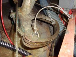
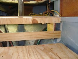
Here's the issue though. The 32-2 manual shows tall vertical stops that are glassed in at the bottom and bolted up on top. I don't see how I can get in there to install something like that! Maybe I can... but it looks like pulling a bulkhead out of the way to get in there will also require it to be reglassed when completed. Argg. I suppose that it may just have to be done.
I did have a thought though. I thought that if I found some sort of arm that I could clamp onto the upper part of the shaft, I could mount it high enough, just beneath the cockpit deck, that I could mount some simple stops through the cockpit floor and be done with it. This seems like it would actually be a simple and efficient system. Much better than tall vertical stops that greatly decrease access to that already cramped space.
Anyone heard of something like this that I could use? It really could come from a non-marine application I guess. As long as it's aluminum probably. Thoughts?
According to the manual, the shaft is 3.5" wide. I would need to verify that with a tape measure as it seems a bit large.
I had some trouble uploading images so here is online album links.
http://i939.photobucket.com/albums/ad237/elsmanwaterman/Ericson Fun/IMG_20131013_172050_298.jpg
http://i939.photobucket.com/albums/ad237/elsmanwaterman/Ericson Fun/IMG_20131013_172111_526.jpg
http://i939.photobucket.com/albums/ad237/elsmanwaterman/Ericson Fun/IMG_20131013_170007_864.jpg
Thanks for your reply.
Steve
Last edited:


