davisr

Member III
I am currently researching my options in terms of rewiring my E25. One feature that I would like to add to the boat is a shore-power receptacle, so that, in the modest coastal cruising that I am planning on doing, I may stay overnight in transient slips from time to time for the purpose of recharging the batteries. I have been reading Don Casey’s books, This Old Boat and Sailboat Maintenance Manual, and have found them to be clearly-written and user-friendly. There are some areas, though, where I could use some additional assistance, one of which concerns shore-power connections to AC systems. Based on everything I have read, this is what I believe I should do (I have included brand names from West Marine catalogue that I have looked through, but have not settled on a particular brand at this point):<?xml:namespace prefix = o ns = "urn:schemas-microsoft-com:oops:ffice:oops:ffice" /><o:p></o:p>

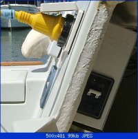
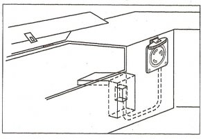
1. Install Marinco brand, 30 Amp shore-power receptacle in cockpit/cabin bulkhead

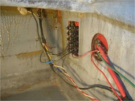
2. Wire shore-power receptacle to Blue Sea Systems brand, AC Main 30 Amp circuit breaker<o:p></o:p>

3. Install several GFCI receptacles in Galley/Main Salon, and then wire them in parallel circuit to AC Main 30 Amp circuit breaker. GFCI receptacles are to be used for power tools, etc when at dock.<o:p></o:p>

4. Install ProSport brand, 20 Amp <?xml:namespace prefix = st1 ns = "urn:schemas-microsoft-com:oops:ffice:smarttags" /><st1:place w:st="on">Battery</st1:place> Charger. The input for this charger is an AC power cord. When connected to shore-power at dock, plug this Battery Charger’s AC power cord into one of the GFCI receptacles so as to power-up the charger.<o:p></o:p>

5. Install West Marine brand, 700 watt power inverter. Either hardwire inverter to battery or join to battery by battery clips. Inverter only to be used for charging of cell phones, camera and video batteries, etc.<o:p></o:p>
<o:p> </o:p>
<o:p> </o:p>
In the wide-ranging and experienced opinion of Forum members, do I appear to be on the mark with these pieces of equipment and connections?<o:p></o:p>
<o:p> </o:p>
Many thanks,<o:p></o:p>
Roscoe<o:p></o:p>
<o:p> </o:p>
E25, cb, <st1:City w:st="on"><st1:place w:st="on">Hull</st1:place></st1:City> 226<o:p></o:p>
 

davisr

Member III
Thanks Loren for responding to my question. I really like the 9x4 box that you built. That sure does seem to be a good location for it, especially since, as you say, the shorepower receptacle would otherwise, on its backside, project into the companionway in an unprotected manner. My shorepower receptacle will need to be placed in almost the same location, so I believe that I will need to follow your lead in this.

Now in terms of the rear panel protection cover that you constructed out of the acrylic . . . where exactly is your panel?

Given the simplicity of my proposed setup . . . I'm thinking that I can get away with using the Blue Sea Systems AC Main + 1-Position Breaker Panel. It about double the width of the AC Main breaker itself that you have pictured on your boat. In other words, I would like to avoid having a separate breaker and main panel. I would like to use the 1-Position Breaker to control the one circuit of several GFCI receptacles.

Does this approach make sense?

Thanks for the helping hand,
Roscoe
 

Loren Beach

O34 - Portland, OR
Senior Moderator
Blogs Author
Thanks Loren for responding to my question. I really like the 9x4 box that you built. That sure does seem to be a good location for it, especially since, as you say, the shorepower receptacle would otherwise, on its backside, project into the companionway in an unprotected manner. My shorepower receptacle will need to be placed in almost the same location, so I believe that I will need to follow your lead in this.

Now in terms of the rear panel protection cover that you constructed out of the acrylic . . . where exactly is your panel?

Given the simplicity of my proposed setup . . . I'm thinking that I can get away with using the Blue Sea Systems AC Main + 1-Position Breaker Panel. It about double the width of the AC Main breaker itself that you have pictured on your boat. In other words, I would like to avoid having a separate breaker and main panel. I would like to use the 1-Position Breaker to control the one circuit of several GFCI receptacles.

Does this approach make sense?
Thanks for the helping hand,
Roscoe
______
Actually, my shore power inlet is on a cockpit combing, just aft of the port side laz. seat hatch. My DC / AC distribution panel is beside the nav. table on the port side of the interior. The added clear acrylic cover over the AC breakers behind that panel was required by modern ABYC and insurability standards. As I noted, it was relatively easy to add. I am not familiar with the DC panel on the 25, but note that the factory DC fuse panel on the E-27 was just inside the companionway on one side. If I were upgrading a 70's Ericson it would be tempting to replace the old fuse panel with a modern breaker panel...
After all, it's only... money.... (sigh)
:rolleyes:

Best,
Loren
 

Glyn Judson

Moderator
Moderator
Terminal block advantage.

Roscoe, Something useful when using a terminal block in areas other than your lighting but still applicable is that an electrical component can be added or removed without disturbing and/or replacing crimp connectors. I've found that by gluing or screwing a small plywood block to the hull or bulkhead, a terminal block can be located on it anywhere it's convenient. It's then simply a matter of installing and then wiring a devise to the block. The result is a very clean and professional looking installation. Good luck, Glyn Judson, E31 hull #55, Marina del Rey, CA
 
only 1 GFCI per circuit

Roscoe,
You do not need to use several GFCIs on one circuit. A GFCI is intended to protect an entire circuit, but it must always be the FIRST fixture on the circuit after the breaker in order to do that. All other outlets/loads must be "downstream" of the GFCI. Put your money somewhere else.
 

davisr

Member III
Thanks Gary for reminding me of the fact that only one GFCI receptacle is necessary in the circuit. I should have remembered that from the way my front porch receptacles are wired. Thanks also Pat for the reference to a ground wire. I'm guessing it can be tied-in to the existing ground.

Loren, you say that your shorepower inlet is on the cockpit coaming, aft of the portside lazarette hatch. Maybe I am mistaking the angle of the photo that you included in your link, but it appears from my perspective that the shorepower inlet is in the portside cockpit bulkhead and that the AC main breaker box is on the port side of the companionway.

Hope you don't mind that I copied one of your photos, but I thought it would be helpful to attach it to this posting for everyone to see what we are talking about. I have also included a picture that shows the interior of my boat. I would put the AC breaker box on the portside of the companionway. This would seem to be the best place for it.

Best regards,
Roscoe
 

Attachments

  • LorenBeachShorePower001.jpg
    LorenBeachShorePower001.jpg
    23.1 KB · Views: 92
  • DSCN7985.jpg
    DSCN7985.jpg
    50.5 KB · Views: 85

Loren Beach

O34 - Portland, OR
Senior Moderator
Blogs Author
It is a matter a perspective, I suppose.
IMO the only important thing is to keep the AC path from the plug to the two-pole breaker short. The most recent ABYC rule I remember is under 10 feet or so.
My new breaker was under a foot... Just a few inches, actually.
---- Being on the box I built to go on the inside of the cockpit combing.

The original panel main breaker is still (redundantly) in place on my factory panel beside the nav desk.

Hope this helps some.

Loren

ps: your boat looks clean and squared away.
 

davisr

Member III
Thanks Loren for the compliment on the interior of my E25. I am fortunate that the former owner (only the second owner) cared for her for many years before having health issues in old age.

I understand now what your are saying about the cockpit coaming location of your shorepower inlet. I have gone back and read (again) through Don Casey's Sailboat Maintenance Manual. On p. 551 he has a diagram that illustrates a set up similar to yours. He has the shorepower inlet forward of the portside cockpit locker. In other words, instead of being on the companionway bulkhead, the inlet is just to the left, where the bulkhead joins the cockpit locker. Therefore, the back of the inlet projects into the locker. Inside of the locker he has drawn a 30-amp main breaker inside of a breaker box. I have scanned his drawing and included it below.

Casey writes: "Despite the tendency of builders to incorporate the AC main breaker into the main switch panel, locating the breaker in a small (household) breaker box near the inlet fitting - typically high in a cockpit locker - gets it into the circuit sooner and is the preferable configuration. You will rarely, if ever, switch this breaker," SMM, p. 551.

I would think, though, that the household breaker box would rust, and that was the reason why you constructed the fiberglass box for your boat. This also begins to touch upon another question that I was going to ask in a separate thread, but will do so now instead. Currently, the backside of the Main DC panel and the Rotary Batery Switch project into the portside cockpit locker in an unprotected manner. Is this normal/safe? I include here a photo (please disregard dirt dobber nests - never had seen these in there until I came back inside the house and loaded the pictures).

Thanks again,
Roscoe
 

Attachments

  • DonCaseyShorepowerDrawing.jpg
    DonCaseyShorepowerDrawing.jpg
    60 KB · Views: 60
  • E25ElectricPix006.jpg
    E25ElectricPix006.jpg
    92.2 KB · Views: 66
  • E25ElectricPix004.jpg
    E25ElectricPix004.jpg
    38.9 KB · Views: 66

davisr

Member III
Having taken another look at my cockpit and having thought through this issue more thoroughly, I now see that it makes a lot of sense to put the shorepower inlet in the coaming, just aft of the cockpit locker. This is where Loren chose to locate his inlet and his custom-built breaker box (as pictured above). I have learned much from Don Casey, This Old Boat, but in my situation it seems if I were to put the shorepower inlet in the spot he suggests (see drawing above), then the shorepower cord, projecting as it would from the side of the cockpit locker, would be in the way of all foot traffic in and out of the companionway.

I believe that I too, in a way similar to Loren, could locate my shorepower inlet in the coaming, just aft of the portside cockpit locker. I also think there is plenty of room in the locker for a breaker box similar to the one Loren constructed. Locating the shorepower inlet here will keep the shorepower cord out well out of the way when stepping in and out of the boat at the dock.

In planning to install this shorepower inlet, I am also considering where I will locate other parts of the electrical system - specifically, the batteries. I'm thinking that I will wire, in a series, two 6V, Trojan T-105 flooded batteries to achieve the necessary 12 volts. It appears that there is not adequate space for two batteries in the stowage area beneath the cockpit. This is where the 13 gallon water tank is located. It is also where the single battery box is currently located. I would like to use this stowage area for tools. There is plenty of space in the portside cockpit locker. I have read other postings on the Forum about the placement of batteries in this location (with venting). I am, though, concerned that it would not be smart to have the shore power inlet and breaker located in the same space as the batteries. It is also in this locker where the backs of the DC panel and the battery switches are located (see pictures above).

So . . . my question is . . . am I right to think that it would not be a prudent choice to locate a battery bank where shorepower breakers and other such electrical equipment is located?

Thanks for any suggestions,
Roscoe

E25, cb, Hull #226
 

Attachments

  • DSCN8101.jpg
    DSCN8101.jpg
    39.8 KB · Views: 375

Krharm

Junior Member
E25 shore power

Rosco,Hey I just put my 25 footer in the water yesterday. I charged the batteries and they were good, the PO had a little solar panel stuck in the window. Not sure if it worked and kept them topped off or not. I have been going thru the same thoughts as you... No major electronics yet ;) but would like to turn on a lite or run a fan at the dock... What have you looked at for solar or is it not an option?Kevin
 

davisr

Member III
shore power, etc

Kevin,

Back in 2009 when I made those postings I researched solar as a means for charging the battery bank. I opted against solar because of its cost and its inability to provide enough amps for the total amp hours I needed. I'm still a non-solar guy, but who knows, maybe I'll consider it again one day.

In terms of shore power and other such electrical issues, my thoughts on wiring scenarios for the E25 have evolved over the past couple of years. If you PM me I can pass along a few items.

Regards,
Roscoe
 

toddster

Curator of Broken Parts
Blogs Author
Hmm... This is a really old thread, but I have been debating this myself for the last couple of weeks. Still working on the cabinetry to contain the 12V stuff though. Loren's threads referenced above make mention of a 3m rule - 3 meters max from the service entrance to the breaker. Somewhere I thought I read that the rule was 9 inches. Could it have changed, or did I get some bad info?

As far as I'm concerned, the shorter distance the better, but the AC panel that I bought just doesn't fit anywhere within 9" of the existing shore power connector. Unless I sacrifice pretty much a whole galley cabinet. There are a lot more possibilities within 10 feet.
 

Loren Beach

O34 - Portland, OR
Senior Moderator
Blogs Author
Elderly Threads and breaker distances

Hmm... This is a really old thread, but I have been debating this myself for the last couple of weeks. Still working on the cabinetry to contain the 12V stuff though. Loren's threads referenced above make mention of a 3m rule - 3 meters max from the service entrance to the breaker. Somewhere I thought I read that the rule was 9 inches. Could it have changed, or did I get some bad info?

As far as I'm concerned, the shorter distance the better, but the AC panel that I bought just doesn't fit anywhere within 9" of the existing shore power connector. Unless I sacrifice pretty much a whole galley cabinet. There are a lot more possibilities within 10 feet.

The maximum distance from inlet to breaker is 3m for your 110 volt AC.

The short max. distance (9") for a breaker/fuse is for 12 volt DC wiring, going from the battery.

I am not an ABYC expert, but that's my understanding of it.

Loren

ps: if the thread is really old, guess I am too! :)
 
Last edited:
Top