• Untitled Document

    Join us on April 26th, 7pm EST

    for the CBEC Virtual Meeting

    All EYO members and followers are welcome to join the fun and get to know the guest speaker!

    See the link below for login credentials and join us!

    April Meeting Info

    (dismiss this notice by hitting 'X', upper right)

Electrical System Question

lindaloo

Member II
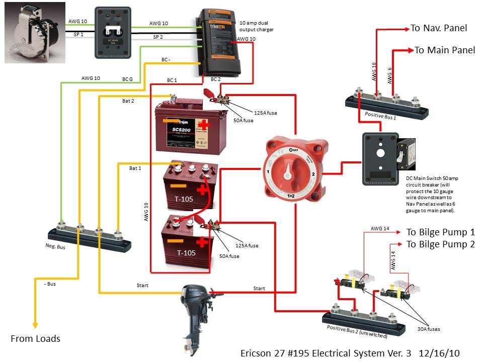
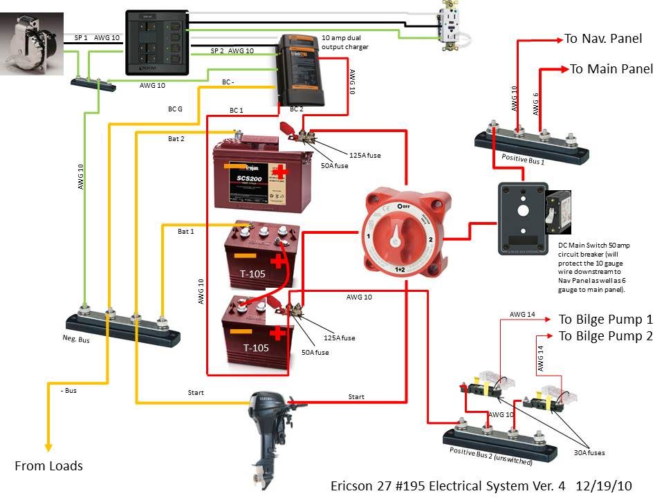
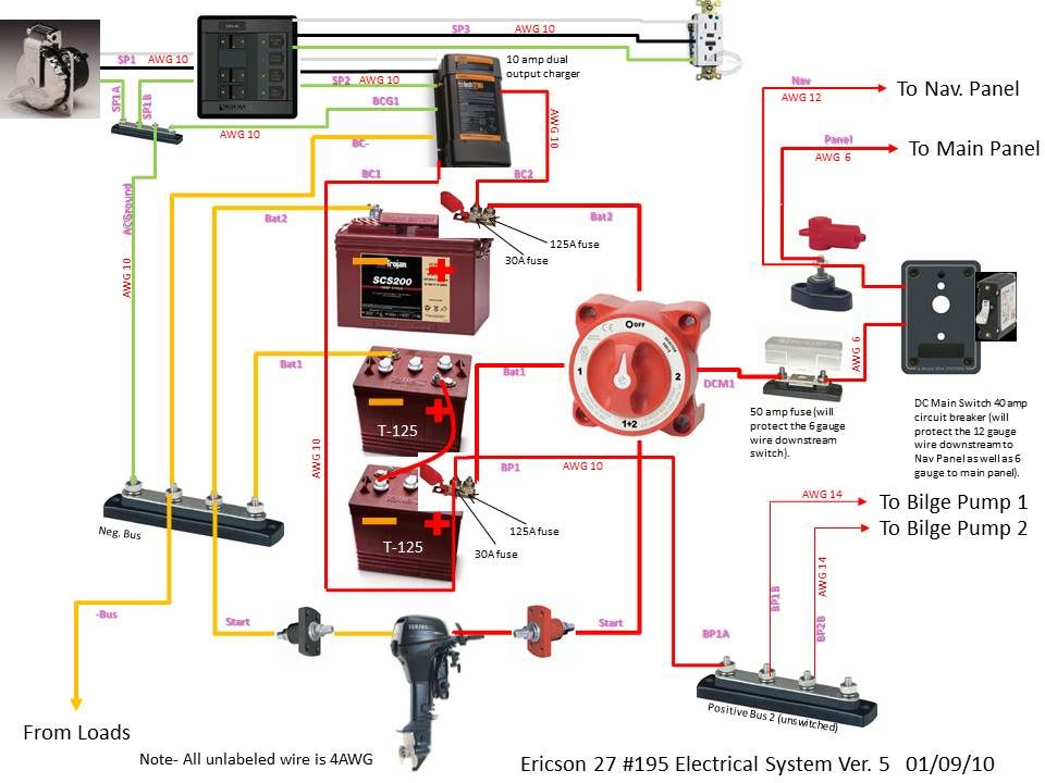
What MaineSail said. Yamaha have been making those High Thrust 9.9's for years. They must be bolted on the transoms of thousands of Catalina 27s, Hunters, etc. From the schematic it looks like you've got the on-motor starter button model. Surely to heavens they have internal protection to keep the charging and ignition curcuits safe from starting currents. Ignition relays, diodes, fuses, that kind of thing.
The Yamaha can take a wave over the powerhead (at a harbour entrance, say, when raising/lowering your main, in blowy conditions), die, then restart without any ill effects. I know because I've done it. Tough motors. Well marinised.
With only one (heavy gauge) wire in and out of the motor for starting and charging duties you have to rely on the engine builder. You can't fuse for both. Or can you?
Interesting thread. Those of us out of our depth are enjoying it. Thanks to all involved !

Rob L.
Vancouver
E34
 

exoduse35

Sustaining Member
Circuit breakers vs circuit breakers...
I just realized my suggestion may have been taken wrong. I envisioned that you were originally going to attempt to create a very simple system, and had elected to run wires direct to the bilge pumps direct to the battery so they would run automatically when you were not at the boat. The type of breaker I suggested is an in-line breaker (a small rectangular can with two screw posts) They react to the heat generated by drawing power, and break the circuit until they cool down then re power the circuit. This is not to be confused with the circuit breakers in the panel (same name, different animal) The one I suggest is only good for a bilge pump application on a boat and only because a regular breaker or fuse can blow and then leave the boat unprotected by the pumps for however long you are away from the boat. Edd
 

bigd14

Contributing Partner
Blogs Author
Thanks MaineSail and lindaloo. I was actually experimenting around with the double switches in response to another post on plasticlassicforum. As I was doing it i was thinking how complicated it was, but went ahead and did it anyways. I am going to go back and modify the original version.

This is a huge learning curve for me so I can't tell you how much I appreciate the advice!

Doug
 

Tom Metzger

Sustaining Partner
Edd - The bad news is that the breakers that you mention are specifically not allowed in the current ABYC spec. This is a good rule because breakers can have a limited life under fault conditions and motors don't generally heal themselves.

<!--[if gte mso 9]><xml> <w:WordDocument> <w:View>Normal</w:View> <w:Zoom>0</w:Zoom> <w:DoNotOptimizeForBrowser/> </w:WordDocument> </xml><![endif]--><!--[if gte mso 9]><xml> <w:WordDocument> <w:View>Normal</w:View> <w:Zoom>0</w:Zoom> <w:DoNotOptimizeForBrowser/> </w:WordDocument> </xml><![endif]-->[FONT=&quot]11.10.1.5 Circuit Breakers[/FONT]
[FONT=&quot]
"11.10.1.5.6[/FONT]
[FONT=&quot] be of the manual reset type except as provided in E-11.10.1.7." [/FONT]

<!--[if gte mso 9]><xml> <w:WordDocument> <w:View>Normal</w:View> <w:Zoom>0</w:Zoom> <w:DoNotOptimizeForBrowser/> </w:WordDocument> </xml><![endif]--> "11.10.1.7 Integral Overcurrent Protection Devices

[FONT=&quot]Integral overcurrent protection devices without a manual reset may be used as an integral part of an electrical device provided the rest of the circuit is protected by a trip-free circuit protection device(s) or a fuse(s).[/FONT]"
 

bigd14

Contributing Partner
Blogs Author
OK, taking into account the information above (thanks again guys!), I have modified the diagram to incorporate hopefully the appropriate fusing and circuit breakers.
I have gone back to a single battery switch. I kept the double fuse setup at the battery terminal, one fused at 50A to protect the 10 gauge wiring to/from the battery charger, the other fused at 125 (could go to 150) to protect the 4 gauge wire running to the switch, starter and bus bars. I also added a DC Main circuit breaker at 50A. And two 30A fuses to protect the 14 gauge wiring to the bilge pump switches which will have a smaller fuse in them (maybe the two 30A fuses are redundant/unnecessary?).

Here is the next version. Did I get this closer to right?

By the way if a wire is not labelled on this diagram its 4 AWG.

E27ElectricalSystemPage1version3.jpg
 

Maine Sail

Member III
Edd - The bad news is that the breakers that you mention are specifically not allowed in the current ABYC spec. This is a good rule because breakers can have a limited life under fault conditions and motors don't generally heal themselves.

<!--[if gte mso 9]><xml> <w:WordDocument> <w:View>Normal</w:View> <w:Zoom>0</w:Zoom> <w:DoNotOptimizeForBrowser/> </w:WordDocument> </xml><![endif]--><!--[if gte mso 9]><xml> <w:WordDocument> <w:View>Normal</w:View> <w:Zoom>0</w:Zoom> <w:DoNotOptimizeForBrowser/> </w:WordDocument> </xml><![endif]-->[FONT=&quot]11.10.1.5 Circuit Breakers[/FONT]
[FONT=&quot]
"11.10.1.5.6[/FONT]
[FONT=&quot] be of the manual reset type except as provided in E-11.10.1.7." [/FONT]

<!--[if gte mso 9]><xml> <w:WordDocument> <w:View>Normal</w:View> <w:Zoom>0</w:Zoom> <w:DoNotOptimizeForBrowser/> </w:WordDocument> </xml><![endif]--> "11.10.1.7 Integral Overcurrent Protection Devices

[FONT=&quot]Integral overcurrent protection devices without a manual reset may be used as an integral part of an electrical device provided the rest of the circuit is protected by a trip-free circuit protection device(s) or a fuse(s).[/FONT]"

Good catch!! I totally missed the "auto reset" part of that. Fortunately, if you stick with products from a company like Blue Sea, you'll only get manual reset breakers.
 

Loren Beach

O34 - Portland, OR
Senior Moderator
Blogs Author
AC question

Hi Doug, One piece I am not seeing is a small AC panel. I know of boaters restoring boats smaller than yours by far that have put in a small AC panel with a breaker for the charger and one for an outlet (or 2) circuit. While you probably will not need (?) a circuit for a water-heater coil... having an option for AC circuit distribution might be a good idea.
:confused:

Edit: BlueSeas PN 1114 might do. Image attached.

Loren
 

Attachments

  • 1114_182x182.jpg
    1114_182x182.jpg
    5.9 KB · Views: 155
Last edited:

bigd14

Contributing Partner
Blogs Author
Hi Loren. You are correct no AC panel. I originally thought about having one but its mostly about finding the space for it (my little panel area is getting crowded!). I have been (unsuccesfully) trying to keep things as simple as possible. Maybe I'll reconsider it and try to find some room somewhere. I guess it would be handy while at the dock.
 

Mark F

Contributing Partner
Blogs Author
Hi Doug,

I have an ac breaker box/panel mounted on the starboard side of the front bulkhead - in the v-berth. It is close to the "chase" that the dc electric lines run through so you can do a fairly clean wire run throughout the boat.

That said if I was starting from scratch I would probably put the ac box in the port lazarette and have the shore power connection on the port side of the cockpit. I had some trouble sealing the shorepower receptacle that is mounted on the cabin side at the head. leaking in the lazarette would be much less of an issue than leaking in the head.
 
Last edited:

Jeff Asbury

Principal Partner
My E-27 must have a deluxe AC set up. The two breaker panel is in the cabinet under the sink. I have four outlets in the main salon, one in the head, one in the battery compartment (perfect for my 3 stage 10 amp charger) and one in the port lazarette. My 30 amp shore power connection is in the cockpit on the port side next to the Yanmar engine panel and shift / throttle controls. Although it appears to be all romex wiring that may have been a upgrade done in the 1980's by one of the PO's. No history on my boat because I bought it as a repo. Every outlet had stainless steel face plates. System still seems to be in good shape. Never had a problem. More AC than I would ever need even if I did live aboard.
 

Don Smith

Member II
AC battery charger

I am in the process of installing a W/M ProSport 12 battery charger in my E26. The charger has a three-prong plug for plugging into the AC electrical receptical. I want to hard wire it into the boat's AC circuit, so I cut off the cord at the plug. I discovered that the power cord has four wires, each individually insulated with the usual rubber coating. One of the, "wires" seems to be made of some sort of fabric.

Question: What is the fabric "wire" for, and where do I connect it?

Thanks for any help you can give.

Captain Don
E26 Gitana

PS: I'll leave for another day the question of whether I've voided the two-year product warranty by doing surgery on the power cord!
 
Last edited:

CWM

Chuck
Doug:

Some comments after rewiring the 12v DC system and installing a 110v AC system in my 1973 E27:

1) I did not run the 110v AC green wire to the negative 12v bus.

2) I only used the buses attached to the new control panels.

3) I used a voltage drop table in selecting 12 v DC wire size:
http://www.solar4power.com/solar-power-volt_drop.html

Chuck
 

Attachments

  • 2.jpg
    2.jpg
    56 KB · Views: 86
  • 1.jpg
    1.jpg
    73 KB · Views: 83
  • 10.jpg
    10.jpg
    94.2 KB · Views: 86
  • 20.jpg
    20.jpg
    85.8 KB · Views: 84
  • 30.jpg
    30.jpg
    96.6 KB · Views: 100

elixirpdx

New Member
Depends

The Cord, and I assume it is in fact a non-conductor, is either used for strength or in the manufacturing process, they used a three conduit wire that had a stripping cord installed to allow the purchaser to strip the outer rubber sheath by pulling the cord to cut the sheath without fear of nicking one of the conduits. If it is a large cord then I would say for strength or I have also seen the mfg put in a 4th cord of a treated wound paper to allow the cord to be more uniformly wrapped. If it is not a conductor then do not worry about it.

Frank
Elixir Ericson
 

bigd14

Contributing Partner
Blogs Author
OK, here is hopefully the last go around. I added an AC panel (thanks for the ideas of where to put it) with two circuits, one for the battery charger and one for an outlet. I also added an AC ground wire bus to collect green AC ground wires to attach to the DC negative. I also realized I could get by with 10 gauge wire on the 50Afuse to the bilge pump bus (instead of 4 guage on the 125A fuse).

Here is the latest version.


E27ElectricalSystemPage1version4.jpg
 

mherrcat

Contributing Partner
It always takes me a while to comprehend electrical circuits, but 30A fuses seem large for the bilge pump circuits; maybe I'm not understanding it correctly?
 

bigd14

Contributing Partner
Blogs Author
Yeah I could probably get by with less than 30A fuse. I maxed it out to wire size. Guess I was thinking that I really only wanted it to blow if there was a major problem since its a critical circuit to stay on. However, downstream there is a 5 or 6 amp fuse in the switch, so I could probably go much lower. Maybe I will plan on a 15 amp fuse. I think I will actually use a fuse block instead of the terminal strip so that i can keep my stereo circuit on as well and maybe something else if needed eventually. Shoot, that means I have to mess with the diagram again. More convolutions! :egrin:
 

davisr

Member III
Big D,

I enjoyed reading this thread back in December. Just curious to know what your final diagram(s) looked liked. Lots of helpful information.

Thanks,
Roscoe

E25, cb, #226
 

bigd14

Contributing Partner
Blogs Author
Hey Roscoe- here are the final plans. I had to add a silly 50A fuse so that i could reduce my wire size to run it to the switch for the DC and Nav panel. I went oversized on most of the primary wire. It was easier (and cheaper) to purchase only three wire sizes (14, 10, and 4 AWG), and just get a few feet of smaller 6 gauge primary wire (which I got from the cut ends section for a discount). I also had to run 12 guage wire to the Nav light panel, since it wouldn't take 10 gauge in the Euro style terminals.

The other sheet didn't change much. Also here are a couple photos of the installation. Enjoy!

Doug

E27ElectricalSystemPage1version5-1.jpg


047.jpg


046.jpg
 
Last edited:

bigd14

Contributing Partner
Blogs Author
I got everything connected today and flipped some swtiches. Lights light up, stereo plays, AC panel comes on, everything runs. Very gratifying, but...

The ProMariner ProTech1210i battery charger does not seem to be supplying a charge to both batteries. I connected it to both banks, jumpered the third output to the second one as per the manual, and fired it up. Battery bank two read 14.58 volts, while bank one only read 12.61. I would have expected both banks to charge simultaneously. I measured at the battery terminals and at the output from the charger. I did not leave the charger on for more than half an hour because I had to leave the boat and did not want to leave it unattended with an untried system running.

Is this normal? Would it eventually switch to the other bank when bank 2 was sufficiently charged? I thought it was supposed to do it simultaneously.

I tried to call customer support but by the time I realized I needed to call them it was 5:03 Eastern time... So I will call them on Monday, but I am hoping someone has any insight in the meantime. Oh and yes, I did read through the owners manual, at least three times! And I have sent ProMariner an email.

Thanks,

Doug
 
Last edited:
Top