• Untitled Document

    Join us on April 26th, 7pm EST

    for the CBEC Virtual Meeting

    All EYO members and followers are welcome to join the fun and get to know the guest speaker!

    See the link below for login credentials and join us!

    April Meeting Info

    (dismiss this notice by hitting 'X', upper right)

E38 quadrant reinforcement pics

rwthomas1

Sustaining Partner
Hello All,
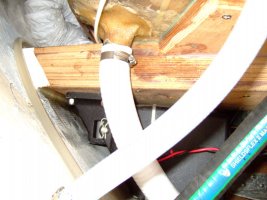
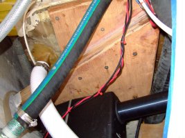
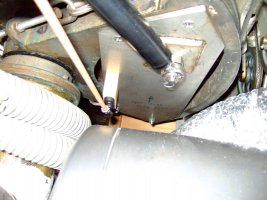
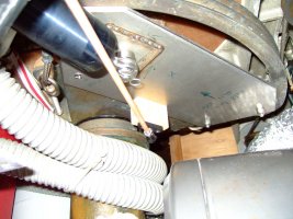
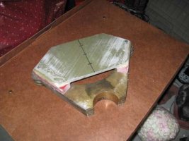
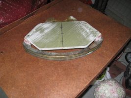
I completed the reinforcement plate to allow the installation of a belowdeck autopilot ram on the steering quadrant of my E38. The reinforcement plate is made of G10 or fiberglass laminate material that is 1/2" thick with additional spacers of the same material but 1" thick. The spacers are required to clear the quadrant stop assembly. This G10 material is extremely tough. I beat on a leftover bit with a large ball pein hammer, hard enough that I would have bent it were it metal, and there was no visible damage.

The plate will be attached to the bottom of the quadrant with (6) 1/4-20 stainless bolts and also glued with 5200 on the mating surface.

Does anyone see any issues with this setup?
Thanks in advance! RT
 

Attachments

  • IMG_0189.jpg
    IMG_0189.jpg
    25.4 KB · Views: 170
  • IMG_0190.jpg
    IMG_0190.jpg
    31.9 KB · Views: 152

jkenan

Member III
The design looks solid, and should hold up just fine. But I'm curious, why did you not go for the separate arm attachment for the autopilot arm? Conventional logic reasons that, should either the quadrant or the arm fail, you have back-up steering with the other attachment. A bit of redundancy.

Also curious, is that the Edson 12" Quadrant? If so, there is one on e-Bay for $129 which would be a steal for anyone in the market for one (perhaps as a back-up, though the bronze ones probably don't fail that often). I'm looking for an 8" for my E29, and buying new seems my only option right now.

Good luck.
 

rwthomas1

Sustaining Partner
The design looks solid, and should hold up just fine. But I'm curious, why did you not go for the separate arm attachment for the autopilot arm? Conventional logic reasons that, should either the quadrant or the arm fail, you have back-up steering with the other attachment. A bit of redundancy.

Also curious, is that the Edson 12" Quadrant? If so, there is one on e-Bay for $129 which would be a steal for anyone in the market for one (perhaps as a back-up, though the bronze ones probably don't fail that often). I'm looking for an 8" for my E29, and buying new seems my only option right now.

Good luck.

Thats a good question! Well, when Ericson built my boat they didn't allow ANY extra room for the separate tiller arm. When that quadrant is installed it sits right on top of the packing flange on the rudder tube. There is only 1/2" or less above it before the top rudder stock bearing in the cockpit floor. I would have to remove the rudder completely and cut down the rudder tube, reglass the packing flange assembly into place, etc, etc. to make a tiller arm work. Sounds like a lot of work in a very small space requiring a high degree of precision. Didn't seem prudent. I am hoping that my plate is plenty strong. That quadrant I am assuming is original and is marked Yacht Specialties. RT
 

msc1212

Member II
I did essentially the same thing when I installed a hydraulic ram onto my edson quadrant last year. The only difference is I used 1" marine plywood that was bolted to the quadrant. The ram works great. I've had it running in some fairly extreme conditions without problems. The fun part was installing the four bolts- the location did not allow for the use of two hands. It took an hour to install each bolt with one hand including the lock washer and the nut. Edson does not recommend using bolts on their quadrant because the required holes can weaken the quadrant. While this is a valid concern I couldn't see how drilling four 1/4" holes along the leading edge of the quadrant and then adding 1" of plywood across the quadrant would weaken the structure.
 

stbdtack

Member III
e 38 autopilot

Did the same thing in 1/4" stainless.....Im thinking the quadrant is stronger with the added plate.
 

Attachments

  • ap mount1.jpg
    ap mount1.jpg
    115.4 KB · Views: 140
  • ap mount2.jpg
    ap mount2.jpg
    138.3 KB · Views: 125
  • quad mount.jpg
    quad mount.jpg
    116.6 KB · Views: 266
  • quad mount2.jpg
    quad mount2.jpg
    130.9 KB · Views: 1,134

rwthomas1

Sustaining Partner
Ben,
Nice work! Thats a fun area to work in, eh? Your ram mount on the hull side looks like way overkill. How many layers of ply is that? Looks about 3 inches thick? I did my mount with one piece of 3/4 ply but heavily tabbed to the hull and inner bulkhead. Doesn't move when I stand on it so I think its good.

With the offset of the ram mount on the quadrant, is the ram angled in relation to the centerline of the boat? Looks like it is... That must have been fun to figure out too!

I will have pics of my setup once my rudder comes back from Foss and gets reinstalled.

RT
 

stbdtack

Member III
yep its tight down there. Those attachment bolts require patience. The mount is 6 layers thick because I needed to drop the ram down to be parallel with the plane of the quadrant. It gave me a broad area to epoxy to the hull as well as a large area to attach inboard under the cockpit floor (plus I had a big sheet of 1/2" marine ply laying around)
Yep the Pin mount is offset because my ram is angled aft in relation to the beam. I did this to get a clear shot to the quadrant. I layed it out on CAD and then plotted it all full size on paper. (measure 50 times, cut once...)
The tedious process payed off as the autopilot steers better than any Ive ever used.....

Looking fwd to pics of your new rudder.

ben
 

rwthomas1

Sustaining Partner
Excellent! I used the opposite approach. The ram is mounted on a shelf that is tabbed to the hull and then the inner bulkhead. I mounted the ram on top of the shelf and slightly offset aft as per the instructions. FWIW, I ended up with a Simrad hydraulic setup with split ram and pump, that is, the ram is connected to the pump with hoses so its easier to mount. My shelf is forward of the outer cockpit drain and more perpendicular to the centerline of the boat. I'll get the pics up when the whole shebang goes back together. RT
 

stbdtack

Member III
Ted,
I have a Raymarine S1G /type 1 drive and 6001 control head. Gyro is the key, Its amazing how fast it responds. I see all the new Raymarine pilots have the gyro included.
 

celtium

Member III
Raymarine S1

Ben,

Did you have any issues with the S1G install? Another person (Capt Ron?) on the forum made note that the E38 has a 13 1/2" swing and the S1 only has 12". Did you adjust for that somehow or just not worry about it?

I'm getting ready to change out my wheel unit before the warranty runs out and any input would be great.

Also, it appears that the unit is installed on the starboard side, the pictures don't seem to indicate or that it simply is a cramped area :) the unit is aft of the hot water heater?

Thanks

Jay
E38-200
SF Bay
 

stbdtack

Member III
S1g

Jay,
the travel of the linear drive is 12" and Im guessing you mean 13.5" swing at the fwd edge of the quadrant. I simply moved the attachment point towards the rudder post(smaller radius, shorter arc) until I got about 11 7/8 travel when the rudder went stop to stop.

This gives the drive the strongest mechanical advantage without hitting its internal limits when the rudder is hard over.

Yes its on the stbd side as there isnt any room on the port side because of the aft cabin. Its very cramped to work in:mad:

All the stuff cleared the hotwater heater which is mostly fwd.

Ben
 
Last edited:

rwthomas1

Sustaining Partner
Jay,
CaptRon used a type 2 long stroke Raymarine linear drive. I think that it has a 14" stroke. I considered the S1G Raymarine package with the type 1 Raymarine linear drive, with the 12" stroke. When I did the math on my E38 the Ray type 1 would have needed to be mounted 9" from the rudder post center on the quadrant to maintain the 12" or less stroke.

I ended up with a Simrad AP24 head, AP42 computer and the HLD2000 long/split hydraulic ram with 14" stroke. So far I have been very happy with the build quality of the Simrad gear and the system is quite overspec'd/overpowered for the E38. It is purportedly rated for continuous duty and will operate in any condition imaginable. I'll have to see about that one. This system was not cheap however.

RT
 

celtium

Member III
Thanks

Unfortunately, when I bought the vessel I got penny wise and pound foolish and bought the 'less expensive' wheel unit from Raymarine, so now to stay in warranty (since it broke 12 hours into my northbound bash between LA and Point Conception:mad:) and with the system computer on board I want to be penny wise again, but hopefully not pound foolish and use the S1 unit. Ben has had good luck with the Raymarine S1G, so I'm going that direction as well.

Does anyone have a template of the quadrant plate they would like to share?:egrin:

Thanks - great subject!!
 

stbdtack

Member III
Jay,
The drive units are sized by the boat displacement. E38 is well under the 22,000lbs the type 1 drive is rated for. A type 2 would certainly steer the boat well but you would need the larger Course computer to handle the higher amp draw of the bigger drive. All much more $$.
Also I'm not sure I want that much thrust pushing/pulling on the quadrant. (1050lbs vs 650lbs) In an emergency the skipper can overpower the Type 1 clutch with a firm grip on the wheel. This has kept me off a couple of crabpots when i wasnt paying attention. I doubt you could overpower a type 2 clutch.

I was concerned about the power of the type 1 as well, but after lots of use, including down the CA coast in 30 kts and following seas, I'm completely satisfied with the performance.

BTW you can upgrade to a gyro by adding a fast heading sensor. functions the same as having the Gyro mounted on the pcb.

I lost my cad files of the quadrant plate in a HD crash, but I have a re-drawn one thats pretty close if you want....

ben
 

rwthomas1

Sustaining Partner
Jay,
The drive units are sized by the boat displacement. E38 is well under the 22,000lbs the type 1 drive is rated for. A type 2 would certainly steer the boat well but you would need the larger Course computer to handle the higher amp draw of the bigger drive. All much more $$.
Also I'm not sure I want that much thrust pushing/pulling on the quadrant. (1050lbs vs 650lbs) In an emergency the skipper can overpower the Type 1 clutch with a firm grip on the wheel. This has kept me off a couple of crabpots when i wasnt paying attention. I doubt you could overpower a type 2 clutch.

I was concerned about the power of the type 1 as well, but after lots of use, including down the CA coast in 30 kts and following seas, I'm completely satisfied with the performance.

BTW you can upgrade to a gyro by adding a fast heading sensor. functions the same as having the Gyro mounted on the pcb.

I lost my cad files of the quadrant plate in a HD crash, but I have a re-drawn one thats pretty close if you want....

ben

That is interesting information. I didn't use the S1 setup after a bit of research.... Raymarine only wanted to know the displacement of the vessel. Simrad asked about 50 questions such as the area of the rudder, LWL, rudder design, force to move rudder, etc. etc. I wanted to use Simrad's HLD350 drive which is comparable to the S1 but this data pushed the application to the larger HLD2000 drive. This required the larger computer, etc. similar to the Raymarine type 2 setup. I priced the Ray type 2 and decided for just a bit more I could have the Simrad. I came very close to just going for the S1 since others have had luck with it however I have heard some horror stories about the drives and Raymarine in general. Lots of Simrad pilots on the commercial boats around here too. Given the very tight spaces to work in I didn't want to do this again or often so I ponied up. That said, I am glad the Raymarine works for you! I am looking forward to seeing how the Simrad works too.

RT
 

celtium

Member III
Smart Heading Sensor

I called the Raymarine Tech Support said the part is called 'Gyroplus II External Rate Gyro Processor' Part #E12101, MSRP $809...but wait...I have a Port Supply Card, yahoo!!!:egrin:
 

stbdtack

Member III
ultimatepassage.com has it for $1.40 cheaper than portsupply but more importantly, no sales tax if youre not in Ohio. And Lisa is so nice to talk to... Ive given up using portsupply for electronics.

Rob, I think Simrad/Robertson makes some of the best pilots out there. In sure yours will perform better than you expect. Curious how your drive attaches to the quadrant plate. I drove a Hinckley 52 with a hydraulic Simrad and it would break the attachment stud mounted on the Edson arm. The stud couldnt handle the shear loads from the ram. It usually broke off at a perfect time, like offshore in bad weather at night. Carried spares until I had a new arm bored at a slight angle. This brought the end of the arm up enough to allow the drive fitting to slide between the upper and lower parts of the hollow arm and still be horizontal. Then I drilled and put a 1/2" SS clevis pin all the way through. Never had a problem after that.
I carry a spare stud now for my raymarine just out of habit:rolleyes: I dont think an E38 will have nearly the same loads as that 52 but those Hydraulic drive units are strong....

Looking fwd to hearing how yours performs! (and see some pics)
 

celtium

Member III
Thanks

Thanks to both of you for the input!! Now I have to put it all into motion starting Saturday by removing the old wheel mount and ordering accordingly i.e. the replacement unit from Raymarine due to warranty and the gyro from ultimate passage.

My buddy in NY, also my boats electrician, has hi praises for the group on this website regarding your willingness to help and your superior boat knowledge:nerd:, koodoos!!
 
Top