• Untitled Document

    Join us on April 26th, 7pm EST

    for the CBEC Virtual Meeting

    All EYO members and followers are welcome to join the fun and get to know the guest speaker!

    See the link below for login credentials and join us!

    April Meeting Info

    (dismiss this notice by hitting 'X', upper right)

Improved Control Cable Run

u079721

Contributing Partner
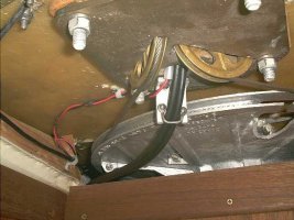
After a very long Saturday afternoon aboard, I finally was able to install new engine control cables aboard my E-38. On of the original cables had snapped right where the factory had run it through a 3" diameter bend, in spite of the Morse spec that the bend be no tighter than 8".

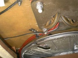
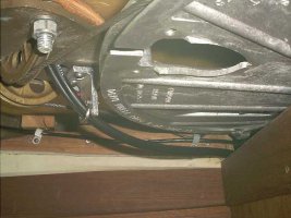
For the new cables I went with Teleflex Xtreme cables, with an 4" minimum bend radius. Even so, I felt I needed to find a way to run the cables through a much more gradual bend. Previously they were held above and out of the way of the radial drive by a metal strap. To give me more room, I fashioned a short 2" bracket to hold the new cables below the radial drive. The difference in the amount of force required to work the gear shift is just amazing.

If you're interested, I have included before and after pictures.
 

Attachments

  • after 2.1.jpg
    after 2.1.jpg
    32.1 KB · Views: 896

u079721

Contributing Partner
The first photo was one of the afters. Here is the other.
 

Attachments

  • after 1.1.jpg
    after 1.1.jpg
    34.5 KB · Views: 864

Loren Beach

O34 - Portland, OR
Senior Moderator
Blogs Author
Nice photos!

Thanks for the help. I plan to replace both my cables before next season. The factory did my cable installation just like yours.
:(

Loren in PDX
'88 Olson 34
 

sailingdeacon

Member III
Seems my 87 E34 is the same thing. But mine snapped at the threaded end at the binnacle. Question: is it possible to pull the entire inner cable out, and replace just the inner cable? I know I should replace the whole think, but then I may not.

Another question: After taking off the compass and looking down into the Edson pedestal I see what appears to be a clamp open on one side through which the cable goes. It seems to be part of the pedestal and is about 10" down. How do I remove the cable from it and how do I insert another?
 
Last edited:

u079721

Contributing Partner
Doubt you could replace just the inner core

I sort of doubt you could replace just the inner core of the control cable. There wouldn't possibly be enough clearance to fasten the old and new together to use the old one has a leader, so you would end up having to push the new core through. And while that might be possible if the cable were laid out straight, it would be very difficult if the housing were still bent at a sharp angle in the binnacle. That resistance is what caused our old cables to snap in the first place.

So I wouldn't recommend trying it, as I think in the end it will end up being more work. Threading the new control cables through the binnacle is the easy part, using the old ones to first install leader lines to help out. The only real hard part of the job is working at the top of the binnacle, just inside, with the plate that fastens the control cables to the binnacle housing. To get the room to do this job I found I had to back off on the steering control cable turnbuckles to creat enough slack to be able to life the steering chain off of the cog, and put it out of the way. After that I had enough room to do the job. So once you get over the inertia of having to loosen the steering cable the rest of the job is straightforward. Not fun mind you, but something that you will appreciate having learned how to do for future reference.

Nigel Calder actually recommends that we all replace our control cables every FIVE YEARS! When is the last time you every heard of someone at the yacht club doing that? He says you should then keep the old cables aboard as spares - a great idea. I replace both when I did it, and bought a third to have aboard as a trustworthy spare.
 

u079721

Contributing Partner
That's what I used

Those instructions are the same as I used, and they explain the process of moving the chain out of the way to get at the cable holder. It isn't as complicated as it sounds from the instructions, so don't worry.

The resulting motion on the gear shift cable was so smooth that I could actually feel the transmission go into gear on the cable. The throttle cable will need to be controlled to avoid slipping down to idle, either with the friction screw on the throttle in the houseing, or using a cable clamp on the cable (which is what I used).

Good luck.
 

sailingdeacon

Member III
Well, the deed is done - after two very long days! Wow what a job. I did have to loosen the cables to pull the chain up to provide space. Why Edson would imply that may not be necessary is beyond me. Heck, I barely got the bar in and out with the chain pulled over! And the most outrageous job in the world is putting that bolt from the cable connection in the pedastal into that hole. A tip to others. You will need some sort of rod to push the bolt into the hole - mostly done by feel. And it is impossible from topsides; do it from below.

Also, after such a job, I simply put the cables back in the same place without the neat fitting you used. I did use xtreme cables though. But I must say that Ericson's access to all the other stuff was relatively good. I understand some other boats are much worse. Not being to handy around mechanical projects, I am exhausted!
 

ted_reshetiloff

Contributing Partner
I just removed my cables yesterday and it was a bit of a PITA. Getting the cable securing block up past the chain sprocket was tough. We did not remove the sprocket as the instructions implied it could be done without doing that. I think though for the reinstall I may remove the sproket though. It would make things a lot easier. u079721 (Steve I think?) gave me the part numbers for the teleflex cables he used and I pulled mine to measure and check against what he used on his 38. My cables were 17 and 18' long. Steve I think you said you used a 13 and a 16 is that right? The cables do take a big U turn in the aft locker then run fwd to the motor so I could probably shorten up some but 4 feet, Im not sure.
 

clayton

Member III
I posted info on this for my 32-200 this past summer, search for "shifter cable replacement 32-200" for an inexpensive cable source (Teleflex). My original cables were both 17 feet, with a big arc under the fuel tank of extra cable. Wound up going with 15 feet for the shifter control and 17 feet for the throttle cable, and still had some extra. Working in the pedestal definitely the hardest part. I didn't remove the sprocket either, just pulled the steering chain off and forward.
 

ted_reshetiloff

Contributing Partner
I think I am going to make them the old lengths just because I don't want to get them half way in and find out one is too short. I made the bracket yesterday and will order the cables today.
 

u079721

Contributing Partner
I looked up my notes on the project, and I used a 17 foot cable for the throttle, and a 14 footer for the clutch, but my notes say that a 13 foot would probably have fit better for the clutch. Teleflex Tfxtreme CC63317 and CC63314.
 

ted_reshetiloff

Contributing Partner
Thanks Steve. I ordered the longer ones 17-18' but I can use the extra to keep the runs out of the way and turns wide. Still need to mount the bracket I made. How fun was drilling and tapping that bronze plate on your back in the aft bunk? I am going to wait to get the cables in to get the angle right on the bracket.
 

ted_reshetiloff

Contributing Partner
Finished up the job yesterday and discovered that with the new cables the throttle slipped. I then discovered that who ever installed this portion of the pedestal had it backwards because the tension bolt was on the gear shift side (port). I had to reverse the top housing to be able to use the tensioner. The best part was today I called Edson to try and order new bushings for the shifter and throttle levers. The person who answered the phone was able to help me immediately and is giving me the bushings shipping included. They sell for $5 each in their catalog but the gentleman I spoke with said he would give them to me, just wanted my address to ship to. Every once and a while I am just blown away by a great customer service experience. Granted it is pretty rare these days but when it happens it makes me want to tell everyone I know how great this company is. BTW I have no affiliation with Edson.
 

sailingdeacon

Member III
I'm confused... you mention a tension bolt on the pedestal. The Edson pedestal on my 1987 E34 does not seem to have anything like that. I had to place a tension bold on the cable itself near the engine to prevent slippage. A little more help please?
 

ted_reshetiloff

Contributing Partner
http://www.edsonintl.com/EdsonMarine/pdf/Instructions/EB396EngineControlInstr.PDF

Here is the instruction manual for doing the cables. If you look at the right side lever in the picture on page one you see a hex head bolt going into the bushing for the throttle lever. There is greater description on this component further on in the instructions. The housing shown in the picture on page one can be installed in two ways, but is designed to have the throttle lever on the starboard side. On my boat it was assembled backwards and a cable clamp was added for tension to keep the throttle from slipping not sure why this was done unless someone simply did not fully read the instructions from Edson. If for some reason your model does not have this it can easily be added. You would remove the throttle lever and associated bushings. Drill a hole and tap it for 1/4-20. Reinstall bushings and lever assy. Then insert a 1/4-20 bolt with some antiseize on the threads and tighten until you get the desired level of resistance to keep the throttle from slipping.
 

mkollerjr

Member III
Blogs Author
re: bracket

It appears the factory learned something between 1989 and 1990, or someone else was on shift for my boat. On my E38, they just notched out the rear bulkhead to allow for a more gradual bend out of the binnacle. You can see how the cable housing has some minor chafe though on that sharp metal plate opening. I may need to do something about that... Other than that, the factory routing seemed to have no drastic bends.

IMG_1530.jpgIMG_1528.jpg
 

u079721

Contributing Partner
Well that does look like quite an improvement over my factory installation. But it still seems poorly done to not have anything to hold those cables and wires from potentially chafing on the radial drive wheel. I mean, it's not like it never moves!
 

mkollerjr

Member III
Blogs Author
Yeah, I'll be sure to secure the cables as needed to prevent chafe. However, he original cables showed no chafe at the steering quadrant (hard to tell from the photo, but there's actually a bit of a gap). Also, it looks like our wood trim is a little different. My removable access panel slopes down towards the aft, creating more room under the quadrant. It looks like yours was more level, creating the need for a tight bend radius.
 
Top