I didn't mean to insult such a legendary engine. Mine was an atomic bore because it needed to be rebuilt and all the periferals were rusting off. My old engine was actually rebuilt and installed in a beautiful restored wooden sloop. I opted to change out for deisel because ultimately, that's what I wanted.
You are using an out of date browser. It may not display this or other websites correctly.
You should upgrade or use an alternative browser.
You should upgrade or use an alternative browser.
Remote Lift Station or Exhaust Riser Saga
Brisdon
Did you install a remote lift station under the cockpit in front of the
fuel tank or go with the original exhaust riser (pics please !)
My parts supplier and rebuild mechanic are WARNING me of ALL the
problems associated with the historical water vapor problems on
the mid engine E35-II exhaust exit run.
The M4-30 had obvious water vapor piston damage
My documentation indicates that Ericson tried several exhaust riser
designs to correct the problem.
My repower to from A4 (cute Flathead) to M4-30 in 1990 has a lift
station above the engine exhaust hose in the bilge. (WRONG !)
The water is always in the exhaust hose like a "P" trap below the
engine. Vernalift indicates that the exhaust hose MUST drain
DOWN to the lift station intake (just good design) to keep water
vapor out of your engine.
Any advise on this much appreciated !
I sawed out the old exhaust system and installed a new Vernalift which has it's fiberglass canister secured just foreward of the under deck fuel tank. The hose rises up to just under the starboard cockpit seat and there it tees with the vent loop from the exhaust water. From there it goes down hill to the stern of the boat where it has it's outlet in the ussual place under the transom. This vent loop spill over scheme is an unusual but useful contraption installed for me by a diesel mechanic friend of mine. I ran this exhaust system for two years with the old Atomic four before installing the deisel. There is a high gooseneck where the exhaust comes out of the manifold before the cooling water pours into the pipe. I have never had water go back into the engine. If you were to grind the engine without starting it for a long time with the seacock open, this would flood the engine. Sooo.... one doesn't do that. Theoretically, with the vent loop attached to the high point of the exhaust before it comes back down to where it fills the exhaust line, it acts as a spill way. If the water in the exhaust pipe should rise up into the gooseneck at the exhaust outlet, it will block the flow and the water will then start spilling from the loop into the upper pipe leading out of the boat. I don't know if any of that makes sense, but you are welcome to come up to LA and take a peek at the installation.
E35-II Exhaust Riser
Thank you Brisdon ! It all makes sense
Can you please describe the exhaust piping OUT of engine and IN to the
Vernalift. This seems to be the potential problem area for me
My lift station is in the same location as yours and I like your piping OUT
of the Vernalift to the exhaust outlet design
Smooooth Sailing
Hey Chaco, the exhaust is pretty simple. I couldn't find a cast gooseneck for the manifold that fit in the confined space between the engine and the side of the box, so I made it out of 1-1/4" galvanized water pipe. It's basically a nipple with an elboe, with a nipple with a street elboe, then another elboe, then a nipple, than a tee, than a nipple with the exhaust hose attached with clamps. The tee is as far down away from the goose neck as I could make it. There is a half inch pipe threaded into the side of the tee (I think I put a reducer in it because I couldn't find a 1-1/4 X 1-1/4 X 1/2. Anyway, the hose with the salt water spills in at that point, just before it converts to rubber hose. The hose turns and rides horizontally below the cabin sole and goes into the side of the Vernalift. Yes, I guess there is water sort of permanently in the horizontal section of the hose. Theoretically that water could create dew in the exhaust manifold and in the engine cylinders as valves get left half open where ever the engine stops. Not sure what to do about that, it is what it is. The old style exhaust where water never entered the exhaust system but cooled it from an exterior jacket just didn't work out very well. They were hot and they corroded, and they took a lot of space and had to be cut out in chunks when they went bad and were almost impossible to install whole in a finished boat when they were replaced. Everyone has just sort of excepted the new configuration as the least of all evils. You can run the engine for a little while after you shut off the engine water and most will blow out of the pipe if you are worried about the humidity. I don't worry about it at all.
Yo Brisdon !
Thanks for the lowdown ! My rebuild shop mechanic has run in to this exhaust/water vapor problem many times before. He wants to elevate the
exhaust outlet out of the bilge to a point above the lift station and drain
DOWN under the port birth. Will be challenging to keep my nav station
accessable ! Will survey the design and see what works.
My project now is to make a new engine bed out of SS L.
The starboard mounting frame sitting in the bilge idea really sucks.
So I will avoid this by cross frames to get out of the bilge.
Will attach SS L feet to the cross frames and attach SS L engine stringer to
the feet. Will rework the port side mounts probably from scratch.
Glad its Winter so I am not missing warm sailing time !
thx
I put my engine on wooden stringers, glassed in. I like them because they can't corrode and they insulate some of the vibration. I think what your mechanic is proposing about the exhaust is esthetic heracy. There were 600 of these boats made and everyone else is fine with the exhaust under the sole. Vapor shmapor. If the geometry between the engine outlet and the vernalift remains the same, what difference is the hose angle between them? You can't get the can any lower, and you can't get the engine any higher, so it is what it is. If the hose under the sole has a little water laying in it after the engine is shut off, what of it. The can is full of water, and there is an open pipe between the can and the exhaust manifold, and that is true of any boat.
Vernalift Wet Exhaust Design
In talking to the Design Engineers at Vernalift the issue seems to be
that the exhaust piping out of the engine needs to drain DOWN to
the lift station (Vernalift Installation Fig.3) to empty the exhaust
piping of standing water which can cause water/vapor drainage back
in to the engine. The E35-II has the exhaust outlet at the same level
as the lift station inlet with a P-Trap of standing water in between.
Check out the site www.centekindustries.com.
All of our boats are full of design compromises which actually work
with what we have to deal with
I agree that hacking up the NAV Station to accomplish a design
directive might not make the the "A" list of things that get done !
Thanks for your support and sharing ideas
Attachments
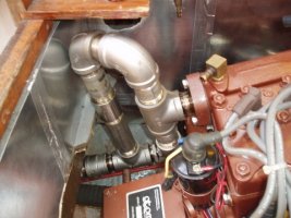
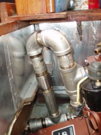
The key is to have the goose neck go up from the manifold (as high as you can get it without hitting the bottom of the plywood under the seat), and then make a 180 and come down. That gives you the dam you need between the engine and the vernalift. The diagrams from Vernalift show the pipe going strait down from the engine, but that standard configuration doesn't really work on these boats with the mid engine arrangement. Sorry to be confusing.
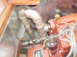
Here is an example of a similar exhaust setup from my E-35 II Atomic 4 engine. It is formed from stainless steel pipe fittings which I ordered online, and cost about $125. I have subsequently wrapped it with fiberglass tape insulation. I put in a little pipe stub below the exhaust flange, something like a sump, with the idea of catching any condensation.
Attachments
-
 Exhaust1.JPG153.1 KB · Views: 142
 -
 Exhaust2.JPG159.8 KB · Views: 149
That looks very similar to what I have (except I don't have the little sump extension on the bottom). It's always worked great for me. I didn't use the stainless though. I had a similar arrangement on my old atomic four and when I took it out after five years, the galvanized water pipe was still almost like new, so I just made the new one for the deisel the same way. I have mine wrapped in that fiberglass muffler tape so that it doesn't toast the wood and heat the cushions. It's been a charm. Thanks for the pictures!!
NateHanson
Sustaining Member
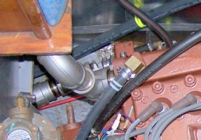
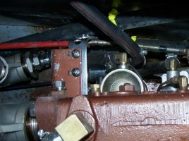
Where is the water injection port on that setup? I'm trying to make sense of it.
The injection port is on the bottom right of the second photo. I can't find the photos I took before I installed it, but here is a diagram I'd made when ordering fittings. Also, here are some closer photos of the hose barb fitting for the water injection. I hope that helps.
Attachments
-
 100_1847.JPG170.5 KB · Views: 145
 -
 100_1878.JPG177.2 KB · Views: 157
 -
 P9230002.JPG154.3 KB · Views: 145
 -
 exhaust setup.GIF5.9 KB · Views: 153
NateHanson
Sustaining Member
Ok, thanks. That makes sense now.
Did you guys use the insulated fiberglass tape that sets up hard, or the soft fiberglass material that is sort of stiched over the hot exhaust?
Nate
Did you guys use the insulated fiberglass tape that sets up hard, or the soft fiberglass material that is sort of stiched over the hot exhaust?
Nate
Tom,
How did you construct/rebuild your starboard engine mount stringer and port
engine mounts. My starboard stringer is TOAST and the port mount beds
are rusted badly. I am rebuilding the engine bed for a Universal M4-30.
Original engine was A-4. Same footprint, just needs to be elevated 1"+/-
for the transmission flange. I will use 2" welded SS L for the project.
Any help on this E35-II Mid Engine Mount would be appreciated
Thank you for the pics on the exhaust riser.
I used the soft fiberglass tape from West Marine, and secured it with wraps of stainless steel wire, which was included.
My engine stringers were rusty, especially the starboard one, but when I ground it down to bare metal there was still enough there to make it worth keeping. I primed it with Rust Knock Out, and painted it with barbecue grill spray paint. Now that the 'new' engine is in, and it is fresh-water cooled, I hope to have less water in the bilge. Maybe that will mean less rust.
If my engine stringers had been in bad shape, I would probably have kept as much in place as possible, and bolted on a stainless steel L bar. But with all the metal out, I think I'd do the epoxy-encapsulated oak rather than metal. That way, if it turns out too tall, you can take a hand planer to the stringer and knock it down to where you want it to be - too low and you could build it up higher. With stainless steel, you better shoot a little low because it is really hard to make steel change its mind once it is in place.
I think I'd still use independent engine mounts rather than bolting the engine directly to the stringers, especially with a diesel, as it should reduce a bit the concussive thudding of the engine underway. Keeps the beer from foaming up and out of the bottle. One of the benefits of the Atomic 4 is that it is one smooooooth engine. Can't always tell if it is running, especially if the radio is playing.
Thanks Tom,
Will mount engine to Bushings Inc. 2205-2 Mounts (www.bushingsinc.com)
Support rails 2"SS L. Legs 2"SS L. Starboard cross supports 2"SS L. The
cross supports will be glassed in to the hull and get me out of the bilge. Port legs will be glassed in with 4"x4" 1/8"SS foot. My starboard rail and support legs are beyond repair. All engine bed will be new construction.
Made an alluminum template attached to the prop flange for mount
locations. Will send pics as project progresses. Engine still in shop waiting
for rebuild or new engine verdict. /)
jmoses
Member III
Word of caution
I highly recommend a siphon break on the E-35 mid-engine install which I don't see in the depicted exhaust diagram.
Since the A-4 in the E-35 MKII basically sits below the water line, it is pretty important to install a siphon break in the water injection line. This will prevent water from siphoning into the exhaust then into the engine when the sea cock is open and engine off (espceilly on a port tack with the exhaust manifold and piping/hoses almost completely underwater!).
Also, another word of caution: with a very short run of injection hose to the exhaust pipe, the engine will back fill with water very easily when cranking the engine for any length of time with the sea cock open. ONE MUST BE VERY CAREFUL WITH THIS SCENARIO!
I have seen a few A-4's back filled with water in a rather short time by excessive cranking (won't start scenario) combined with a short exhaust pipe and an injection point near the manifold. It only takes a few minutes of cranking to destroy the engine with water and break the valves (water doesn't compress).
I always recommend closing the sea cock when excessive cranking is required to prevent back filling the engine.
Ideally, there should be a loop in the exhaust above the water line as well with the injection hose run above the water line with a siphon break to prevent a nasty siphoning back fill of the engine scenario -it does happen! Seen it several time as well.
As an aside, I ran an exhaust loop up above the water line in the stbd cockpit locker to get a portion above the water line when on a hard tack. IN addition, the injection hose runs up to the same vacinity as well with a siphon break in the injection hose BEFORE injecting into the exhasut pipe/mixing can. In essence, the raw water/injection hose exits the engine, runs up the to stbd locker above the water line (near the ice chest), passes through a siphon break, then returns to the mixing can at the engine exhaust manifold. It then exits through the exhaut pipe and out the stern.
This routing also provides an extra margin when cranking the engine as the raw water must pass through about 8 feet of 1/2" hose before back filling the engine through the exhaust mixing can at the manifold.
Oh...one last word of caution....you may want to insert a pencil zinc in the exhasut system's metal piping connected to the engine, especially when using stainless steel. The heat, disimilar metals (cast iron, steel and stainless) combined with hot corrosive exhaust gas and salt water will ensure galvonic corrosion of the metal.
John M.
What about your prop pitch?
You have sucessfully replaced your A4 which was probably a direct drive like mine. Did you repitch your prop? If so what did you end up with? My original A4 is a two blade.
Thanks to everyone for your help with engine selection for my 35-2. I've been so busy, I've forgotten to post an update. Those rusty metal stanchions under the starboard side of the old Atomic Bore, that I was worried about finally gave way last summer. We were going almost nine knots on a port reach and poor old Stinky just rolled over on her side against the engine box. I ended up putting in the Universal M3 20B. I thought it might be a little under powered but I liked the fact that it would actually fit in under the seat without a lot of modifications. All I had to cut out of the lid was a little patch over the alternator. The little fiberglass bubble that we made to cover it, just hides under the cushion. It turns out, the 20 delivers plenty of power. It tops out at about 6 knots, but 5.5 is really comfortable for a long motor. Really happy with it. That single improvement has completely changed the boat for me. It burns about .6 gal. per hour when I'm really pushing it. Just amazing. We put the engine in with the boat in the water, so I haven't replaced the shaft log yet. Finally taking it out next week to put in a PYI in place of the packed shaft seal. Can't wait to have a dry bilge. Thanks again y'all.
You have sucessfully replaced your A4 which was probably a direct drive like mine. Did you repitch your prop? If so what did you end up with? My original A4 is a two blade.