• Untitled Document

    Join us on April 26th, 7pm EST

    for the CBEC Virtual Meeting

    All EYO members and followers are welcome to join the fun and get to know the guest speaker!

    See the link below for login credentials and join us!

    April Meeting Info

    (dismiss this notice by hitting 'X', upper right)

E38 Universal 5432 engine mount concern

Neil Gallagher

1984 E381
Hello Folks

While servicing the heat exchanger this weekend I noticed tha the engine appears to have shifted to the port side. I also noticed that the engine mount lag bolts do not seem to stay tight. I have had to tighten them up at each service interval. Has anyone else experienced this? Is the engine bed solid fiberglass or wood underneath? I am concerned that the engine alignment has shifted although there is no engine vibration while under power. Would longer lag bolts solve this issue? The attached picture shows how the forward engine mount has moved, note the bolt is on one side of the engine mount slot. I’m sure the engine will need re-alignment but it seems the mount issue need to be resolved first. Any guidance would be appreciated.
 

Attachments

  • ECE6B7E9-924D-4B84-9026-6D5805CF1F7A.jpg
    ECE6B7E9-924D-4B84-9026-6D5805CF1F7A.jpg
    44.6 KB · Views: 315

footrope

Contributing Partner
Blogs Author
Is that mount collapsed?

From that angle at least, the mount in your picture looks collapsed or just plain worn out. I'm not a mechanic, and maybe it's just the angle the picture was taken. If it is worn out that may be part of the reason the lag bolts are getting loose - no damping of the vibrations.

The first picture I attached is my front mount. Note that it is installed at a 90 degree angle to yours. I also have a decent picture of my left engine mount. They seem to be working well and the mounting bolts are not loosening. (It's probably time to replace them after 13+ years.) I was told by the shop that my original front mount was oriented in the wrong direction and they installed it the way you see it with the bolts left and right. I have no particular opinion about which is the right way, so you might seek professional help with that. But, making that change may help you avoid some repair work in that front rail if the existing holes are too sloppy. I see most of the 38s with companionway engines are installed like yours and the way mine used to be. Just an idea that has worked for me for 13+ years and hundreds of engine hours.

20150624_204325-crop.jpg

20160708_184707-small.jpg
 

Neil Gallagher

1984 E381
Thanks Craig that’s a great idea to rotate the forward mount, I will consider it. Will also need to check out the aft mounts. I believe the PO changed the motor mounts so I don’t they are collapsed. However I hate the thought of having to pull the engine to deal with this. More to come....
 

footrope

Contributing Partner
Blogs Author
I checked the hole in the forward rail and there might be wood in there. It was kind of hard to tell and I didn't have a drill to use to probe a little. Even with a pick and a flashlight I couldn't figure out what was under there. Hope everything turns out OK.
 

EGregerson

Member III
mount

Hi Neil; check the link Bigd14 showed; you can see the variety of issues with the mounts; or more properly, the lag screws into fiberglass and wood. If u can remove the motor, you can do a proper job like Ian S did. Short of that, it's pretty much "roll your own". Until i can lock in a solution i feel comfortable with, I just inserted a larger diameter lag screw. After a year it still seems to be holding pretty well. Lots of ideas and approaches on the issue here. I'd like to be able to drill access holes in the stringer, thru bolt the mount, and have a fabricated plate to cover and reinforce the access hole. But for now... well, the larger lag screw is holding. :)
 

JSM

Member III
West System Method

As soon as Chicago weather permits I will be converting the 3 point mounted M25XP in my 34-2 to 4 mounts and installing new Vetus K75 mounts. The forward mounts will be bolted into 3"square steel bearers that will be drilled and tapped to accept the bolts.
Two years ago I had the rear mounts out and I am afraid that the holes will not tolerate another in/out trip by the lags. My plan is to either replace the lag bolts with epoxied in hanger bolts or if possible (without removing the engine) use the West System method for epoxy bonding studs.


https://www.westsystem.com/instruction-2/epoxy-basics/bonding-fasteners-hardware/
 

Navman

Member III
5432 engine mount

Neil,
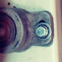
I had the same problem with my engine mount lag bolt. The port side lag was stripped out and I could not get a larger lag in due to the constraints of the engine mount and its bored opening. I poked and prodded and found there was no bottom to the bed log. I could stick a coat hanger down through the hole and it would hit the bottom of the hull.I did NOT want to have to remove the engine nor detach the mount.I decided on a few options and began exploring feasibility of same.
Option 1: was to drill out the engine mount hole to accept a larger diameter lag.
Decision: I did not think that after drilling there would be enough metal left in the mount between the wall of the newly drilled hole and the outside of the mount. Not enough" meat". I also did not like the idea of simply putting in a larger lag into wood ( of unknown species) that has already been compromised. I also could not figure out how to get a drill into position to do the task. The area is too confining.
Option 2: Try to figure out a way to temporarily block the bottom of the hole with an epoxy coated material to form a plug and let it dry. After curing I could fill the hole with epoxy and then insert the old lag while still wet I would have a coating of PAM on the lag so it could be removed. After the filler dried I could then remove the lag, add a washer and re-insert the lag and tighten it up. I thought that this would be the preferred approach.
Decision: I tried several times to insert different materials into the hole but they always fell through. I tried fiberglass tape saturated in epoxy and pushed it down slightly but it always fell through, I tried a piece of sponge, fell through. I thought of using a spray foam expanding insulation but was not confident it wouldn't also fall through. I surmised that the bottom of the hole must have been flared due to the deterioration of the wood.
Option 3: Insert a dowel soaked with epoxy and drive it into the hole? It sounded like a good idea but I had already decided that I could not get a drill into the area.
Decision: I really liked this idea but kept wondering how I could drill the dowel after it was in. Then I thought what if I could drill the dowel BEFORE I put it in? How does one do that? I gave it a lot of thought and came up with this. While my home is over two hours from the boat and I did not have the exact diameter of the hole, I bought 4 different sizes of oak dowels ( thinking one of them had to be the correct size). I cut 4" off of each dowel to be used. I then mounted a 4x6 block of wood to the table of my overhead drill press so the 6" side was vertical. I will use the 5/8" diameter dowel as an example for the explanation. I drilled a 3-3/4" deep x 5/8" hole into the block. I then used pushed in the dowel. I then secured the dowel from spinning using a drywall screw being careful to only just touch the exterior of the dowel and not penetrate it. I then switched to a 3/8" bit and slowly lowered it down onto the dowel. The result was a nearly perfectly drilled hole in the dowel.
Application: I took my assorted drilled out dowels to the boat, decided which one fit best and scored the exterior of the dowel so as to provide an irregular surface for bonding. I then cut up some fiberglass cloth into tiny shreds and mixed them with epoxy. I also cut a thin strip of epoxy cloth (3/8" wide x 6" long and soaked it with epoxy. I laid the cloth across the lag bolt hole, coated the exterior of the dowel with the thickened mixture, set the dowel in place and began to drive it home using very short raps with a short handled 2lb. lump hammer. When I could not get it down any further I took a wrecking bar and placed it on the dowel and began hitting on it, the bar (offset) about 5" away from the dowel. This allowed me to set the dowel even deeper. I let the epoxy set for 24 hours, said a prayer to all who would listen and set the original lag bolt in the hole and ratcheted it down. I cranked down on it pretty hard and it did not spin. I then cranked down as hard as I could and it held without spinning. I have had the fix in place now for about 100 hours of engine running time and when I check the bolt with a socket wrench it is still secure. I know one day I will have to pull the engine and replace all of the mounts, but am very happy I did not have to do it just for the sake of a single lag bolt.
I hope this helps you with your lag issuesand provides you with another possible solution to consider. GOOD LUCK. As I like to say the thinking usually takes much longer than the doing.
 

footrope

Contributing Partner
Blogs Author
Anybody who does not smile in appreciation of Don's post has never owned a real boat.

I agree and enjoyed the journey. I've taken a few of those journeys myself.

Is there any spouse or significant other of a boatowner who doesn't get exasperated over how long it sometimes takes to make these "simple" repairs?
 

Neil Gallagher

1984 E381
Wow what creativity Navman! I agree, we spend lots more time thinking about solutions than it takes to implement! Thanks for sharing..
 

JSM

Member III
Boat ownership in three words.....Improvise. Adapt . Overcome.

Thanks Navman ! In mental preparation for my upcoming motor mount change / 3 to 4 pt. conversion surgery the rear lags and how to deal with them has been heavy on my mind. Your fix sounds simple and straight forward and leaves me with two questions.
1. What size dowel did you end up using. Did you need to drill the hole out larger to accept it?
2. Approxamatly how thick is the wood that the lags go thru ?
If my holes aren't too bad I may just wet them out with epoxy and drive in waxed up lags and hope for the best.
 

toddster

Curator of Broken Parts
Blogs Author
Argh! This wasn’t even on my radar. But just today I read about a boat sunk by an engine coming loose in heavy weather. I did have a vague unhappy feeling when I discovered the 2x4’s under fiberglass last summer...
One more thing to worry about.

If taking the engine out, why not just hack those things out of there and replace with something more solid?
 

Loren Beach

O34 - Portland, OR
Senior Moderator
Blogs Author
Argh! This wasn’t even on my radar. But just today I read about a boat sunk by an engine coming loose in heavy weather. I did have a vague unhappy feeling when I discovered the 2x4’s under fiberglass last summer...
One more thing to worry about.

If taking the engine out, why not just hack those things out of there and replace with something more solid?

Most if not all builders put solid wood inside the frp stringer moldings for the engine mounts. Best to check the torque on the lag bolts for the mounts every year; a friend of mine sez he does this during the annual oil change when he is already accessing the engine bay.

On our boat this takes a 9/16 wrench (or a deep socket on a ratchet ) and some creative reaching and mild cursing. :rolleyes:
 

sharonov

Member II
The first picture I attached is my front mount. Note that it is installed at a 90 degree angle to yours....
View attachment 23653
Wow! That is a brilliant idea. It is really hard to reach the back lag on this mount to tighten it up. Hopefully it does not reduce resistance to back and forth force that the engine transfers throughout the mounts to the hull. Aneway there are two more mounts at 90 degrees that should handle it.
 

Navman

Member III
JSM,
In answer to your questions; I believe I used the 1/2" dowel it was the same size as the hole in the engine mount foot. I think I used a 1/4" or a 5/16 bit to make the hole in the dowel so there would be enough of a wood "wall" left. I believe that the bed log had a thickness/ depth of approximately 4" due to the fact that the lags were that 3-1/2" long. I did not do any drilling into the foot of the engine mount. Don't know how you would even if you wanted to do to the inability to get a drill in there. I even though of using one of those flexible drill extensions but even it was not able to make the necessary curve.
 

JSM

Member III
Thanks Navman. Good to know. Trying to prepare for the worst while hoping for the best. Sounds like my plan to use the West System method may be thwarted by open lag holes.
 

ConchyDug

Member III
Footrope, I saw the photo of your reoriented nose/fwd engine mount and pondered about it for awhile. I assume this position allows for a more pronounced up/down adjustment for the driveshaft and the l/h & r/h mounts allow for lateral adjusment? It's similar for the turboshaft engines I mess with, just wondering this is good info for future projects!
 

footrope

Contributing Partner
Blogs Author
Footrope, I saw the photo of your reoriented nose/fwd engine mount and pondered about it for awhile. I assume this position allows for a more pronounced up/down adjustment for the driveshaft and the l/h & r/h mounts allow for lateral adjusment? It's similar for the turboshaft engines I mess with, just wondering this is good info for future projects!

Hi ConchyDug,
Welcome to the board again.

The orientation of the mounts on the beds isn't so important for the adjustments we make to line it all up through the hull and strut. The mounts have to be in a certain place in the compartment so that the engine sits really close to what is required. Then the nuts are adjusted to get the prop shaft and transmission couplings aligned within a few thousandths of an inch. Yes, the front is for up-down height and thus the "pitch" angle. The side mounts are to get the holes in the couplings aligned. The perimeter of the couplings have to match closely. The whole engine can be rotated laterally too, due to the slop in the brackets on the engine. Lateral movement is more of a nudge action, though. Loosen all three top nuts and shove. The lateral alignment is the hardest due to the fact that it requires brute force to make the adjustment. The 5432 engine weighs over 500 lb.

I thought about the orientation of the front mount a little too. I wonder if the mechanic that re-oriented the front mount was not telling me that the reason for the change was to resist torque. The mount has to resist fore and aft thrust also, but maybe torque is a larger, or higher impulse, force. I really don't know if either way is better for that front mount. The most obvious explanation is that the holes in the beds were getting sloppy, but I don't know that for a fact. As soon as he looked at the engine mount he said it was worn out and needed to be mounted sideways.

Turboshaft engines - like on a big ship?
 
Top