aj vollmer
Member I
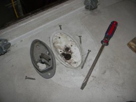
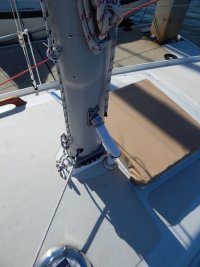
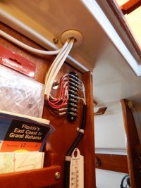
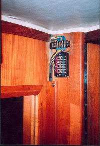
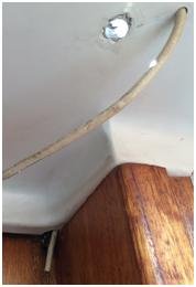
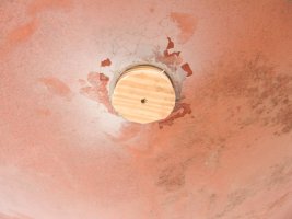
I am rewiring the mast lighting on our 1976 E27 and need some information. Some previous owner gave up on whatever the orginal plan was, drilled holes in the mast 3 inches up from the base, ran the wires a short distance on the deck, then drilled holes so he could run the wires into the head. Just a horror...
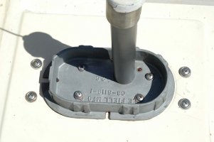
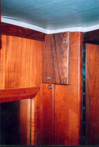
For those of you who have pulled the mast on an E27, can you please tell me what was the original way the electrical wires went into the cabin from the base of the mast?
I've looked and can't find anything obvious so that I can reconstruct what was originally there.
Thanks as always for the help.
Andy