• Untitled Document

    Join us on April 26th, 7pm EST

    for the CBEC Virtual Meeting

    All EYO members and followers are welcome to join the fun and get to know the guest speaker!

    See the link below for login credentials and join us!

    April Meeting Info

    (dismiss this notice by hitting 'X', upper right)

Battery short

sjconnor

Simon Connor
Hi all,

I found something weird happening with my battery, there's short happening somewhere. I took this vide and posted it to youtube to show what's happening and would appreciate any advice on what might be wrong.

https://youtu.be/FOGkkngUi1s

Thanks and best regards,
Simon.
 

Loren Beach

O34 - Portland, OR
Senior Moderator
Blogs Author
Hi Simon,
I am having some difficulty with the video - it's not you, it's me...:rolleyes:

If I understand you, both batteries actually "test" good when you apply the meter to the battery terminal. Have I got that right?
And, you have two 12 volt batteries in the factory position in front of the engine, functioning as two separate banks unless you combine them with the main switch?

On my sister ship, there is a #14 (or 16, carries no real load) red wire from each positive post on the master switch over to the panel where both wires go to the little bat-handle switch that uses the meter to measure one or the other.

I have made one change in those circuits - I fused both wires close to the master switch so that they meet ABYC standards. A few years ago I also replaced my volt meter when the original one got flakey due most likely to internal corrosion and a loose internal connection.

Is your master switch (which looks like my original one) working ok and sourcing either battery as you choose?

The terminals are very close together on the back of that large red rotary switch -- I presume that nothing is touching between those swaged connectors?
(I only ask because that master switch is exposed to hands and tools used in and around the engine.)

Meanwhile, perhaps I'd better study the video some more.....
:)
Best,
Loren
 

Guy Stevens

Moderator
Moderator
You don't talk about load power or what is happening.

Ok this is going to be a little hard without photos, or drawings... I don't have access to that tonight, so lets try and reason it out.

First question do the loads power off of the battery #2 when you switch to #2? The Battery voltage guage is a seperate entity in most cases, and this could be the issue.

How this normally works:

Battery #1 and #2 share a common ground, normally the engine block. (This is bad for a whole host of reasons, but we are not going to get into that now).

So the battery voltage gauge measures between a lead connected to either directly to the battery, or to the lug that is on the back of the battery switch. (Through a fuse hopefully).

So when off, the battery 1 voltage works as we would expect, however battery #2 does not work.
When on #1 Same as above.
When on Both, suddenly both #1 and #2 have voltage. This is not true, actually at that point you are most likely measuring the battery voltage on #1 through the battery switch to the lead for the #2 battery on the volt meter on the panel.
When on battery #2 you have no voltage reading on the panel. (Note for all of this tell us if when on #2 do you have power to the other loads on the panel?)

Most likely battery #2 is not connected to the switch, or not connected to the ground on the engine. The panel voltage meter is connected to the back of the switch, and is working as we would expect there. OR the battery switch has packed it in.. Looked like a cheap guest one, so that would be a normal failure mode too. Lets do some more troubleshooting and fix a few easy to fix things along the way OK?


Does any of that make any sense?

Thanks,
Guy
:)
 
Last edited:

Guy Stevens

Moderator
Moderator
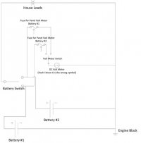
OK so here is a drawing.....

Visio-Basic-Battery-Drawing-Ericson-site.jpg

This should be how it is wired.... Lets start with this... Then lets look at where your problem is.....

Guy
:)
 

Guy Stevens

Moderator
Moderator
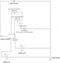
Cause #1

Basic Battery Drawing Ericson site showing open.jpg

This is if the Positive Lead from battery #2 is not hooked up. This is a likely scenario.

(Note it could also be the Negative Lead from the battery to the Engine block Also).

Guy
:)
 

Guy Stevens

Moderator
Moderator
Or

The other likely option is that the #2 lug is melted on the back of the guest battery switch and only connects when the battery switch is in the both position. You would not be the first person to have this happen.

However I would check the wires from the batteries to the the switch first, and the batteries to the central ground lug, (Most likely a bolt on the engine block).

Thanks,
Guy
:)
 

Guy Stevens

Moderator
Moderator
Terminology

Also the battery #2 situation you have is an open circuit not a short circuit. (Short circuits blow fuses and start fires, and are the opposite of this problem).

Not being pedantic here, just trying to make sure that we are on the same page with our terminology.

Thanks,
Guy
?:)
 

sjconnor

Simon Connor
Hi Guy,

Thanks for taking the time with your explanations and questions. It looks like I should go down and do a little more testing and research on the problem and report back. I shall explore this further and look at power to the switch board and engine (beyond the power to the voltmeter as shown in the last video).

Best regards,
SImon.
 

hodo

Member III
Hi, Just by watching your video, I would say your wiring is incorrect. You should not have any reading on battery test meters with master in Off position. Access your master switch, and start from bare terminals. By the way, Disconnect all leads from batteries and use your ohm meter to verify wires. Are both batteries same design? Deep cycle or starting,? otherwise you will run into charging issues, as they need to charge at different rates, times.

Harold, Mischief :devil: Maker
 

Tom Metzger

Sustaining Partner
Are both batteries same design? Deep cycle or starting,? otherwise you will run into charging issues, as they need to charge at different rates, times.

FWIW, if both are flooded cell lead acid batteries they will charge properly in parallel if they are mixed starting and deep cycle, different sizes, etc. Each battery will take only as much current as it needs. They should not be paralleled if they are not being charged.
 

sjconnor

Simon Connor
The good news is its fixed. The bad news is it was because I was stupid :)

Previously I had seen a negative cable from the switch going to each of the batteries, and so I removed the one joining the batteries via the negative terminals (assuming it was redundant). The problem was of course Bat 1 was negative connected to the engine Ground and by disconnecting the two batteries I'd removed Bat 2 connection to the Ground which is why there was no voltage reading at the test meter. So I just reconnected the negative cable I'd recently removed and hey presto (surprise surprise :) )

Guy - thanks for your advice - it made me focus on the circuit being open instead of shorting.

Hodo - the test voltmeter on my switch panel was one I had installed and wired directly to the batteries so no need for the Isolation switch to be on.

Loren - first thing I did was to check the switch and ensure nothing out of the ordinary was going on there, so thanks for your advice too.

Next I'm gonna get a couple of battery boxes to put them in to protect them from water and also protect them from myself :)

Cheers,
Simon.
 

sjconnor

Simon Connor
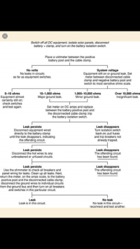
Ground Leakage Test process

Finding that my batteries were discharging at a rate that just didn't make sense I started to do some testing. I followed the process below and found that I had major ground leak - not relating to the cabin electrics but only the engine.

IMG_4484.PNG

Measuring the resistance between the disconnected Positive cable and the connected Negative Cable - the resistance was 150 Ohms, not much at all, indicating a pretty direct link between positive and negative circuits.

Knowing that I had added this new Panel for my Volvo Penta 2002 engine, where I had previously a basic panel (no Temp Gage or Oil Pressure Gage) I was curious about whether the fact that I didn't have these gages before and hadn't installed the required sensors onto the engine for Temp and Oil Pressure - whether those could be causing the ground leak.

So I disconnected the plug from the Temp Gage and measure the resistance again - it was 1, indicating an open circuit, ie no ground leak. So I disconnected also the Oil Gage for good measure and I hope this has gone some way to resolving the problem.

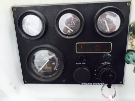
However - I have found something else strange - in the photo below, the key is in the off position, and the engine is not running, yet the voltage is showing 11V and the lights to the panel are on. The battery is a brand new battery charged to 13V. According to the user manual for the Volvo Penta 2002 when the key is in that position there should be no power to the panel, so the Voltage should show zero and the lights one the panel should NOT be on.

FullSizeRender.jpg

Appreciate if anyone might have any ideas on what could be happening here, remember that I went from a basic panel to the deluxe panel, the cable is the same model.

Many thanks,
Simon.
 

Loren Beach

O34 - Portland, OR
Senior Moderator
Blogs Author
Hi Simon,
I passed this thread along to my very experienced marine mechanic friend for any comment.

Perhaps there is something amiss in your particular engine's senders/transducers. (Or the wire run itself?)

Anyhow here is his initial take on it:

" I have found going from a simple warning light system to a gauge type system for oil pressure and temp, the sending units are from a simple on /off sending unit to a variable voltage type which means their the current flow to the gauge is determined by pressure or temperature. where most marine instruments use the amount of current flow to ground which increases the gauge position, Some Volvo systems use a two wire system which sends a current to the sender and back to the gauge. A given pressure or temperature controls the amount of current flow through the sender. If the old senders are used with the new gauges ,it's possible that one would have current flow straight to ground on both gauges causing a drain. "

I must admit that I have never owned a small Volvo diesel and have zero first hand experience with them.

Good luck on your trouble shooting.

Loren
 
Last edited:

sjconnor

Simon Connor
Hi Loren,

Thanks that definitely reinforces what I found that when I disconnected the the two new instruments from the old sensors the leakage seemed to have gone.

I shall order the new sensors as having oil pressure and temp would be useful.

Why the power to the panel when the key is in off position is still a bit of mystery. I've installed an inline on-off switch and placed it through the hole for alarm test button as a temporary workaround.

Thanks for your quick action on this question Loren.

Cheers,
Simon.


Hi Simon,
I passed this thread along to my very experienced marine mechanic friend for any comment.

Perhaps there is something amiss in you particular engine's senders/transducers. (Or the wire run itself?)

Anyhow here is his initial take on it:

" I have found going from a simple warning light system to a gauge type system for oil pressure and temp, the sending units are from a simple on /off sending unit to a variable voltage type which means their the current flow to the gauge is determined by pressure or temperature. where most marine instruments use the amount of current flow to ground which increases the gauge position, Some Volvo systems use a two wire system which sends a current to the sender and back to the gauge. A given pressure or temperature controls the amount of current flow through the sender. If the old senders are used with the new gauges ,it's possible that one would have current flow straight to ground on both gauges causing a drain. "

I must admit that I have never owned a small Volvo diesel and have zero first hand experience with them.

Good luck on your trouble shooting.

Loren
 

sjconnor

Simon Connor
Thanks for your reply, yeah its weird coz these panels come already wired up. It's not like I can mis-wire the panel as its all just plugs which can only go in one way.

I've sent the question off to JustAnswer as well so see what responses that generates also.

Cheers,
Simon.


With a 150 ohms in resistance you will be drawing 86 milliamps. That is nearly a tenth of an amp. I don't know anything about this panel, but, as it should not be on, then that is a good place to look. If there should not be any power there with the switch off, then why is it there? Power is bypassing the switch since that is what controls it.
 

sjconnor

Simon Connor
I've answered inline below.

The main issue I'm trying to resolve now however is to do with power to the panel when the switch is in off position.


1. Am I to understand that you do not have the sensors for the oil and temp installed in the engine? - Correct. I was give the Deluxe panel which has instruments (gauges) that I don't have sensors for (yet)

2. You said the meter reads 1. Usually you will see "OL" when the resistance is out of range for a particular setting on DVMs. I believe some meters will display a 1--- for an open though I may be misremembering this. Maybe this is what you mean. Either way you need to keep moving up in range to see if a higher resistance is present. So maybe you could clarify what you mean by 1, as it is ambiguous. What is the make and model of the meter?

Well the reading went from 150 ohms when the plug from the old sensor to the new instrument in the panel is connected, to 1 on my multimeter (open Circuit) when I pulled that plug out. So major leak resolved. I can switch to higher reading to see if there's still measuring a minor leak, thats a good idea.

3. You said you "disconnected the plug from the Temp Gage". Does this mean you did this at the panel, on the gauge itself? If not, please clarify. At the panel - pulled the plug out from the instrument itself, coz it didn't make sense to connect an old sensor which was for a light only, to an instrument which is supposed to measure temp.

What I know is that, at least on the panels I have worked on, the power to the gauges and lights was supplied by the ignition circuit via the switch, hence switch open, no power. The second pole of the gauge went to the sensor where the circuit completed to the engine ground. If you do not have these sensors in place then you should not have a path to ground.
 

sjconnor

Simon Connor
Wow, thanks for the time in replying, its a lot to try to digest. I'll take it parts at a time and insert my replies below.....


OK, I think the main problem is that you have power applied to the panel when you should not. There should only be power there when you want to use the engine and you turn the switch to do so. If not, what you have is power applied to the lights for the panel and also to the gauges and their associated sending units. This will draw power. From the picture for your panel, it appears that there is a switch for the lights. This should turn off the lights, does it? I can try at the weekend. You need to identify the wire that comes into the panel that supplies power to it. If you can, remove it and tape it off with electrical tape for now. Then apply power and then see it you are getting voltage at the panel, which you shouldn't. I've already identified that wire, and inserted a toggle switch as a workaround to disable the power to the panel as the key system doesn't seem to be doing that. When I toggle that switch to off then there's no power to the panel and the problem is solved. But this shouldn't be required if its all working as it should do without my toggle switch workaround

Here is a basic wiring diagram for instruments.

attachment.php


The power for the instrument lights should come from the switch marked "inst light" on your panel which in turn should be supplied from the main switch on your panel when it is on. If it does not get its power from this switch, where does it come from? Does it come from your main panel? The ground in this diagrams is for the lights. Remember, the circuit for the gauges are completed through the sending units for those gauges via the engine ground. With the power removed from the panel, you should be seeing no voltage there, unless there is something connected to it that is feeding voltage. Use the ground for the lights to probe for voltage. Also, if you disconnected the connection at the gauge and got a different ohm reading, why is that since you said you do not have the sending units for these gauges and hence now path to ground. This should be an open circuit then. See Lorens reply - he'd inserted some text which reinforced that a ground leak can occur when connecting up the new panel to the existing wiring loom, where new sensors are not added. Where is this connecting to give you one reading with it connected and another when it is not? You also said that you were given the panel, does this mean that it is used and not new? Its a second hand panel but only a few years old

PS The volt meter will get its ground through the same path as the lights as it is just measuring the voltage and there is no sending unit for it.
 

sjconnor

Simon Connor
I'm having an electrician come to do some faultfinding at the weekend.

You mention possibly the switch - if by that you mean the ignition switch - thats brand new. The panel is from a friend and that hasn't been modified. Anyway, more testing required and you've given lots of good advice - thanks for that.

To be continued ......
 

sjconnor

Simon Connor
I managed to find a couple of solid boat electricians in Singapore who came down to the boat with lots of test equipment and a great attitude to solving the problem. It took about 4 hours of lots of tracing and testing of all sorts from the engine, fusebox, switch, etc etc, and they found there was a damaged wire inside the short cables that goes from the keyswitch to the panel. All fixed, working as it should now. Engine Ground leak has gone (gauges remain disconnected until I update the sensors for the deluxe panel gauges) and the switch only provides power to the panel when in the 1 position, power is disabled in the 0 position. Interim toggle switch removed as now redundant. Two new batteries installed. Next to replace those sensors, upgrade the existing 80W solar panel to 2 100W semi-flexible panels and replace wiring from solar panels to battery and add a more advanced better quality 2 battery controller/regulator to keep trickle charge on batteries and keep them constantly topped up and also replace some old wiring in the boat - especially stuff like bilge pumps.

Can't emphasise how good it feels to get this sorted and find electricians who are reliable and professional.

Thanks for the advice.

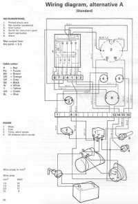
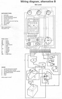
Attached the wiring diagrams for the Volvo Penta 2002 original standard panel and deluxe panel that I replaced it with - this was useful in the troubleshooting process.

Volvo Penta Basic Panel.jpgVolvo Penta Deluxe Panel.jpg
 
Top