• Untitled Document

    Join us on April 26th, 7pm EST

    for the CBEC Virtual Meeting

    All EYO members and followers are welcome to join the fun and get to know the guest speaker!

    See the link below for login credentials and join us!

    April Meeting Info

    (dismiss this notice by hitting 'X', upper right)

E29 Mast Wiring and Deck Step

toddster

Curator of Broken Parts
Blogs Author
Starting an archaeological dig into the mast step and would appreciate any advice from previous explorers. We've got a few days dry weather forecast, so I'm starting in on the deck hardware and sanding. The problem at hand is the mast step and routing wires to the mast. (I've just finished re-wiring the whole boat. Except for this.) The only existing electrical device up the mast is the steaming light which doesn't work. There was a wire for some kind of wind instrument, but it's long gone.

The previous wiring, which otherwise looks to be original, is four wires that ran up the side of the compression post, behind a piece of trim, and disappeared into the liner. When the mast came off, it could be seen that they were routed through one of the mounting holes for the aluminum step, which someone had hogged out with a drill. Wow, that doesn't look very "professional." No drip protection either. No sign of any previous wires though. My guess is that this detail was not found on the blueprints, so the yard guys sort of winged it. I COULD re-use these four wires to get steaming, anchor, and spreader lights with a common ground (all LEDs). But I still need a larger opening for antenna wire. And there are other toys to consider, like the hailer and the GPS antenna.

old mast wire.jpgstep.jpg

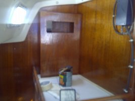
Under the step, we find two more holes, that were full of putty. At the bottom are two bronze screw heads, which I imagine bind the deck to the compression post. No sign of any other previous wiring channel. My first idea is to drill a new hole about where the pointer is there. If those bronze screws mark the center of the compression post, this ought to clear it. (If so, this means that the mast is offset slightly from the post.) After an exploratory hole, I think I'd drill a 3/4 or 1" hole all the way through the shoe, deck, and liner, and install a PVC fitting to act as a conduit and a dam in case of water intrusion. If my assumptions are wrong, it could make a heck of a mess.
new hole.jpg

So if all of the above is correct, the new hole would come out just starboard of the compression post, above the passage way. Depending on where the hole lands, I'd fasten an electrical junction box either to the overhead liner or the side of the post, with a foam backing to fill the irregular surfaces behind. It's more of an obtrusive location than I had imagined. Then I'd have to figure out how to run conduit down and through the bulkhead without interfering with the door, drilling through a structural member, or looking excessively ugly.
post.jpg

As an alternative, I could just enlarge the hogged-out hole that was previously used. The mast has been riding on three screws all of these years anyway... I'm guessing that would cut a notch into the top of the bulkhead and the liner, just forward of the old wires. I'm a bit worried that the drill might cut a corner off of the compression post though. I can't really see what's happening behind the liner. Anyway, the junction box would be less obtrusive in this location, and conduit could just run straight down into the chart table. Or I could enclose it with a mahogany trim piece, sort of as before.

I guess I'll ponder the potentially ugly alternatives for a day or two and hope that someone here has gone there before. Plenty of other bits to work on today.
 

Greg Ross

Not the newest member
Something missing?

Toddster,
Responding from a "work" computer and unable to transfer images from an external memory "stik"
What you seem to be missing on that mast base is a riser sleeve to inhibit moisture from tracking down along the wiring harness.
While you've got the deck shoe off I would suggest having a piece of 3/4 to 1" ID aluminum tubing welded on to the floor of the shoe. Only qualification is with the quality of the casting (purity) it may be challenging to weld. Other option is to have it drilled and tapped NPT (pipe thread) so a nipple can be threaded in. Probably the simpler solution since once fitted there's no load on it an long as you avoid bumping it with the mast either way when restepping.
From what you describe I would be inclined to locate a new hole aft but in line with the screw hole where the wiring was previously run through. Have the hole in the shoe welded/ filled - epoxy/ fill the old hole in the deck to be able to take a new (4th) replacement screw. Finally drill that new wiring hole in line/ angled similar to the existing hole. I wouldn't worry too much about a bit of lost material off the edge of the compression post. The deck should be spreading that compression load and loss of a few percent would be insignificant.
On our Layla the wiring harness is in the head compartment running up the side of the compression post behind a trim piece. There's no conduit below the Mast shoe so I just fish a piece of wire thru to lead any new wires. I would say the riser tube on our step is no larger then about 3/4" ID and I have all the feeds you describe plus Wind Machine and Radar multi-cores.
Another thought is to drill several drain holes low in the skirt of the deck shoe aligned with notches/ half moon cutouts in the base edge of the mast to allow for draining off of condensation.
Last suggestion is to incorporate a multi-prong plug in the harness inside the mast so removal/ restepping is simplified. We unstep - restep annually and this is a must.
I have junction boxes for the Radar and Wind machine cables and access for them is an oval hole cut into the side of the mast, just above the Step. It has a reinforcing lap ring cover and goes on with six fasteners.
 
Last edited:

toddster

Curator of Broken Parts
Blogs Author
Yes, things became a little clearer after I pulled out all the old wire and peered through the hole.

I had thought to just tap the shoe and screw/epoxy in a PVC male thread to female slip adapter as a riser. Cash and time are running low on this project. And it will be loads better than what was there before.

The limiting diameter seems to be the connector on the RJ213 cable. If one bundled the RJ213, the "mast cable" they sell at WM, the wind instrument cable, a speaker wire and a messenger line... good grief, that would take more than an inch hole to fit through. And weigh a ton. I'll be experimenting with some different materials, I think, before I drill.

I like the idea of a junction box inside, so the connections are always accessible. I could save two wires by using a common ground for the three lights, but on the other hand, I don't like the idea of wire splices dangling up inside the mast.
 

paul culver

Member III
I'll confirm the riser sleeves, as my E29 has them. In my case, all of the mast lights' cabling emerges aft of the starboard bulkhead and the vhf coaxial forward of the bulkhead inside of the head.

Paul
E29 "Bear"
 

toddster

Curator of Broken Parts
Blogs Author
The situation changed a bit with my acquisition of a used radar set. The connector for that alone would require at least a 2-inch hole. So I've sent away for two of those green multi-pin military-style cable connectors. One for the radar and one for everything else. I'll pass the cables through and then solder them into the connectors, and leave them sticking through the shoe.

Also had a brainstorm when trying to figure out how to mount the radar dome without interfering with the steaming light or the spin pole topping lift. Relocate the steaming light onto a bracket below and in front of the radome. Mount the hailer upside down underneath the radome. Bolt it all over the steaming light weldment, and use the existing reinforced hole. No new holes in the mast! Well, except for screw holes. More junk up the mast, but at least it ought to stop the main halyard from wrapping around and jamming on the steaming light.
 

Randy Rutledge

Sustaining Member
tabernacle 003.jpg

Attached are pictures of my mast step, it's mounted on a plywood mockup of the mast hinge plate I made. I used two four pin flat plugs like for trailer lights for mast and wind instrument wiring. I used on male and one female on the boat and on the mast, that way I can’t plug to the wrong wiring set. They tuck in the mast base. I had to cut out the stand pipe and mount one in the base of the hinge as the old step is mounted on the top plate of the hinge assembly,
I went to internal halyards so I thought it necessary to install light PVC conduit in the mast with all wiring in conduit to the exit point of the mast. This was a real task as I had to heat and flatten PVC tabs to glue to the conduit for mounting. I screwed the tabs in with screws in the Sail slide track. This required having tabs, steaming light, and spreader light outlet in the correct place.
Make sure there are drain holes drilled in the wall of the step to allow water to escape without rising to the top of the cup the step forms.

tabernacle 002.jpg
 
Last edited:

Emerald

Moderator
The situation changed a bit with my acquisition of a used radar set. The connector for that alone would require at least a 2-inch hole. So I've sent away for two of those green multi-pin military-style cable connectors. One for the radar and one for everything else. I'll pass the cables through and then solder them into the connectors, and leave them sticking through the shoe.

Also had a brainstorm when trying to figure out how to mount the radar dome without interfering with the steaming light or the spin pole topping lift. Relocate the steaming light onto a bracket below and in front of the radome. Mount the hailer upside down underneath the radome. Bolt it all over the steaming light weldment, and use the existing reinforced hole. No new holes in the mast! Well, except for screw holes. More junk up the mast, but at least it ought to stop the main halyard from wrapping around and jamming on the steaming light.

Be really careful about cutting the radar cable - it may never work again. I'm not an expert on this stuff, but when installing my (vintage) Apelco unit, I had the same thoughts on installing a connector, and was quickly straightened out by someone who knew the unit, that the cable must be kept in tact from the dome to the display. It was a royal pain to fish it through, but I did manage to do it. It's a job for lots of beer and coffee. :rolleyes:
 

mherrcat

Contributing Partner
IIRC, every connector you put in the cable attenuates (lowers) the signal a few dB. Better to have a clean run of cable with only one connector on each end. True for VHF as well.
 
Last edited:

toddster

Curator of Broken Parts
Blogs Author
Yes - but there's just no practical way to make a hole large enough to pass that huge connector through. To pass the other end, one would have to fish the whole cable through the mast during every launch. Anyway, I was forced to splice the line already once. The PO (or his rigger) cut the cable instead of spending an extra 60 seconds to open the dome and unplug it. It seems to work OK, but I don't know how I would tell for sure if one of the 16 conductors had a bad connection. e.g. maybe the gain control wouldn't work right...

In any case, I'll test the whole wiring harness before and after pulling it into the mast. And I can probably get a backup cable from ebay. The conductor that I assume to be the main signal wire is a coax with a very, very thin core.

I believe I've read that newer units do a lot more of the processing in the dome, and only a light network cable is needed to connect the display. Seems like a good idea.
 

Emerald

Moderator
I think I was able to disassemble the connector and pull all the pins out of the big plug to get the size down to the OD of the cable, but it was still tedious and a bear to work with.
 

toddster

Curator of Broken Parts
Blogs Author
What's done is done

For better or worse, I hogged out the existing cable path to 1" and added a PVC dam inside the step. I'll experiment with putting a LB connector in there to hold the various cable plugs.
Holy Cow! The good news is that under the mast step is 4.5" thick of solid laminate! Except maybe the top inch is plywood. Probably 4" if the hole were drilled 90°. The bad news is that a significant part of that seems to be this "beam" structure in the liner that runs fore and aft over the z-shaped bulkhead. By drilling this hole, I've cored out a significant portion of it.

In hind sight, I might have preferred a conduit outside the mast step that would avoid perforating this structure. Oh well. If it keeps me from sleeping at night, I guess I can have a steel plate fabricated to bridge the cored area and wrap around the compression post.

new wire hole.jpgnew wire channel.jpg
 

Randy Rutledge

Sustaining Member
Extend the dam you built with a piece of PVC tubing that turns 180 degrees to form a drip loop or at least add a couple of inches and seal the tube end with a good sealer and make sure the wires form an S to allow water that runs down the wire to drip off before getting to the tubing. As I previously stated I have the straight up pipe due to the tabernacle hinge plate not allowing the 180 cap. Also I used four wire trailer wiring connectors for the 8 wires in my mast mounting one male and one female wire connector in the mast and that way I can't connect them wrong.
 

clp

Member III
For what it's worth, there's what mine looks like. Probably not the sexiest thing in the world, but I can get at it, and tinker with it.
 

Attachments

  • IMG-20120511-00232.jpg
    IMG-20120511-00232.jpg
    46.8 KB · Views: 631
Top