• Untitled Document

    Join us on March 29rd, 7pm EST

    for the CBEC Virtual Meeting

    All EYO members and followers are welcome to join the fun and get to know the guest speaker!

    See the link below for login credentials and join us!

    March Meeting Info

    (dismiss this notice by hitting 'X', upper right)

Wiring a windlass....

rwthomas1

Sustaining Partner
Hello All,
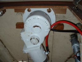
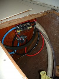
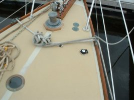
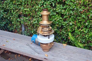
Currently working on a Maxwell windlass install. The schematics and instructions speak of wiring directly to the battery bank, but there is no prohibition of wiring through the battery selector switch..... Is it possible or even prudent to wire through the battery selector switch? It would seem to make sense to do so. It would make sure the power to the windlass was off when the whole boat is shut down. Is this warranted or a possible problem with the failure of the selector switch? The windlass has a 135amp inline CB so I think the selector switch will handle that no problem. The cables from the bank to the selector switch are 4/0 cable, way huge, so current is not a problem. What say the crowd? RT
 

Glyn Judson

Moderator
Moderator
Wiring your windlass.

Rob, You could still shut everything off when leaving the boat without wiring the windlass through your battery selector switch by doing what I did (and I think what most everyone else does). My 1/0 cables lead directly from my Blue Sea power posts http://bluesea.com/category/82/38 adjacent to my battery bank. I have a short cable from the positive post to a 150amp Blue Sea breaker. Power to my Ideal MCW windlass is normally off at the breaker and I would only energize the windlass if I planned to use it. The other benefit of having the power switched off is that I can freely walk around the foredeck without regard for spinning the windlass up or down if I happen to step on one of the two foot switches. My opinion, worth less than Loren's 1 cent. Glyn Judson, E31 hull #55, Marina del Rey CA.
 

lbertran

Member III
Wired To Battery

I just got done installing a Maxwell windlass last weekend and followed the schematic by running the positive cable to the battery rather than to the selector switch. In my case, going to the selector would have added several feet in cable length and keeping the wire run as short as possible is a real plus. As Glyn points out, the Maxwell circuit breaker in the positive cable can be used to de-energize the windlass circuit without shutting off the house batteries. I also installed the Quuick remote control which I'll use instead of foot switches, couldn't bring myself to cut more big holes in my boat! Everything seems to be working and turning in the right direction! I just ordered the rode and chain for the new windlass and can't wait to try it!
 

bob and sharon

New Member
Proper windlass installation

Hey RT, your Maxwell instructions should show a diagram exactly like what libertran and glyn are describing. Always keep the cable run from the battery to the circuit breaker as short as possible, because a short-circuit here will definately cause a fire, use chafe protection if necessary. Athough I have seen windlasses wired to battery switches, I don't advise it, it adds more connections thus more possibilties for problems later on - connections can come loose and burn. Be sure to use the proper Blue Seas cable cap to cover your cable terminals on the back of the circuit breaker, solenoid and on the windlass. One more thing, consider placing an inline fuse in the positive wire the goes from the solenoid to the footswitch or remote plug (a short circuit here will not trip the 100-150amp windlass circuit breaker). And if your windlass is exposed to the chainlocker (read wet), then give everything a good spray with CorrosionX or a similar product. Have fun!
Bob
 

Greg Ross

Not the newest member
Windlass installation

Rob,
I opted to install a circuit breaker immediately adjacent to the "Engine Start Bank" since the engine will be running any time the windlass (originally installed Capstan) is running. The circuit breaker provides protection to everything between the CB (obviously) and the Windlass. Cables were run inside hose for chafe protection for the areas of the installation where I thought there could be exposure to external loads, etc.
I ran those two cables up to the V-Berth void space where I created a mini power center/ pair of bus bars. The solinoid activated by the (covered) foot switch is located here and that secondary switch circuit is energized from this point as well. On deck I experimented with tailing rope looped around the capstan to determine where best to locate the foot switch. The location somewhat aft from the Capstan required a nominal bit of challenge on the I-31 to feed the switch wires over top of the rope locker bulkhead above the ceiling vinyl.
Three images give you some idea of what was involved. The Mustang Capstan is coming off the boat in favour now of a vertical Ideal Windlass (all bronze Loren) c/w 275' of 5/16" chain.
 

Attachments

  • U-S Mustang.jpg
    U-S Mustang.jpg
    75 KB · Views: 137
  • DSCF0044.jpg
    DSCF0044.jpg
    61.6 KB · Views: 155
  • DSCF0050.jpg
    DSCF0050.jpg
    81.8 KB · Views: 109
  • Hull _63, Ideal MCW _1RR.jpg
    Hull _63, Ideal MCW _1RR.jpg
    146.4 KB · Views: 167
Top