It'll be almost 1 year since owning the boat, basically when I got her all of these didn't work (cables disconnected, etc):
- tach
- water temp
- amp meter
- oil
- engine hour
Only thing that worked was the key, glow switch, start. As of last weekend, I'm through the instrument panel/cockpit side of the wiring, and I think I know how everything should work (will upload pics in separate thread https://ericsonyachts.org/ie/thread...rting-w-engine-instruments.20233/#post-160004).
So the cockpit side of wiring, I think I'm good, replaced w/ new wires, new hardware, now it's time to dive deep into the engine bay. Help needed just to figure out what these things are. I've gone through the various Westerbeke manuals for M40, M40_parts_list, M40_technical-man, M50_operator_man, etc, and some of the forum posts. Can't seem to come up w/ what these things are even called, much less what they do, most have disconnected cable connectors.
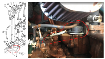
First up, this is under the air filter, close to the glowplugs. Wires disconnected, no idea what this is and can't find it on the parts list.

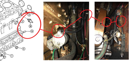
Second up, instead of the "Oil Pressure Sender https://shop.toadmarinesupply.com/ships_store/?p=details&mfc=Universal&sku=299964§ionid=5171", I seem to have a hose connected to something mounted on the wall, again, wires disconnected, anyone know what that's called even?

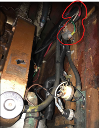
Finally, what does this look like:

- tach
- water temp
- amp meter
- oil
- engine hour
Only thing that worked was the key, glow switch, start. As of last weekend, I'm through the instrument panel/cockpit side of the wiring, and I think I know how everything should work (will upload pics in separate thread https://ericsonyachts.org/ie/thread...rting-w-engine-instruments.20233/#post-160004).
So the cockpit side of wiring, I think I'm good, replaced w/ new wires, new hardware, now it's time to dive deep into the engine bay. Help needed just to figure out what these things are. I've gone through the various Westerbeke manuals for M40, M40_parts_list, M40_technical-man, M50_operator_man, etc, and some of the forum posts. Can't seem to come up w/ what these things are even called, much less what they do, most have disconnected cable connectors.
First up, this is under the air filter, close to the glowplugs. Wires disconnected, no idea what this is and can't find it on the parts list.

Second up, instead of the "Oil Pressure Sender https://shop.toadmarinesupply.com/ships_store/?p=details&mfc=Universal&sku=299964§ionid=5171", I seem to have a hose connected to something mounted on the wall, again, wires disconnected, anyone know what that's called even?

Finally, what does this look like:

